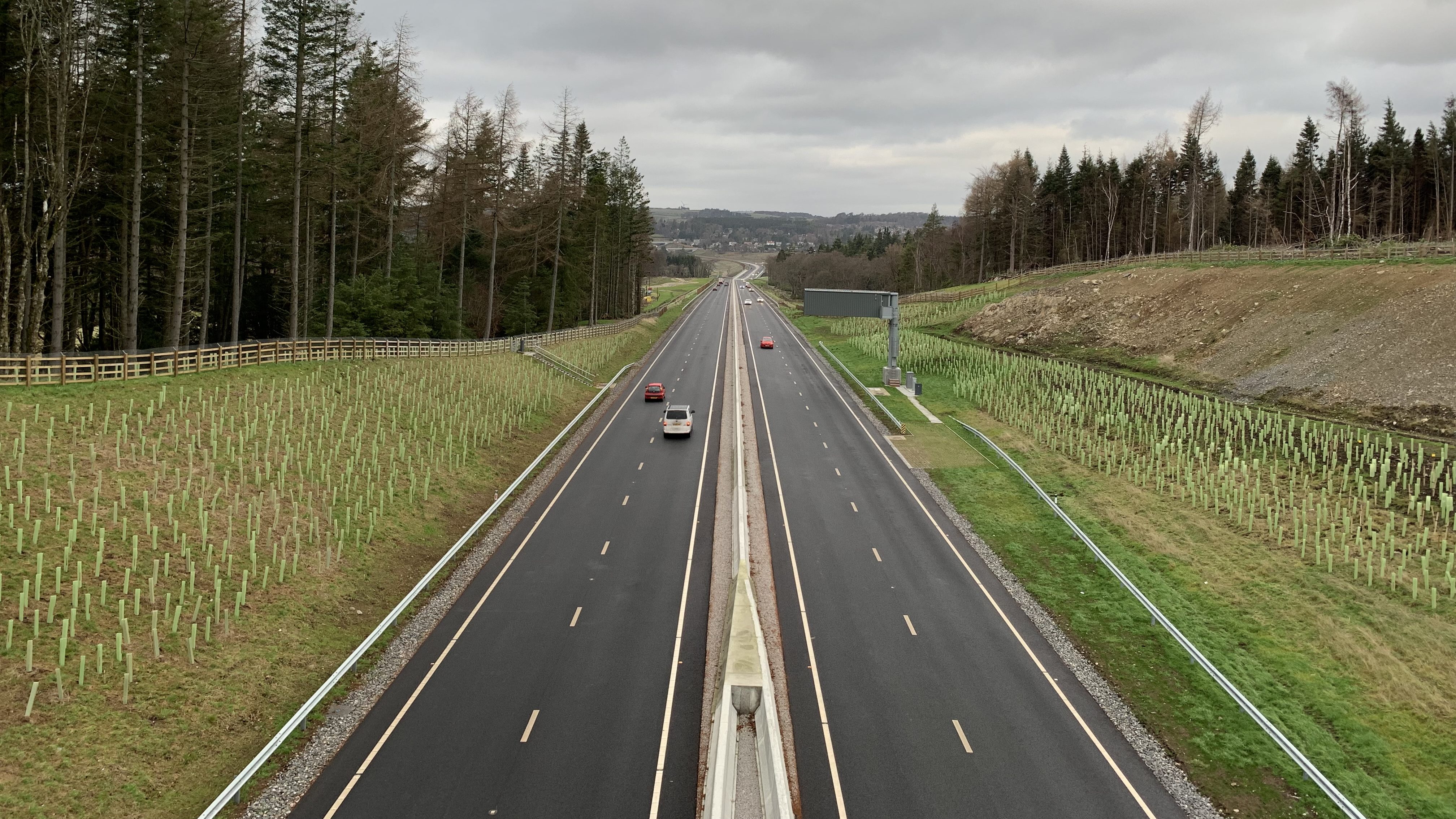
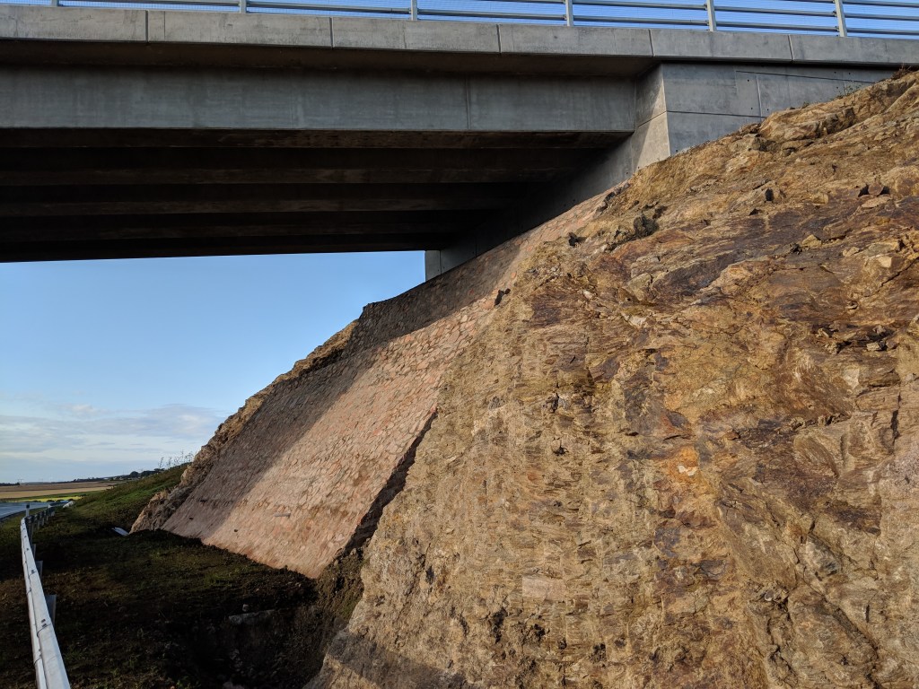
Earthworks are one of the quiet workhorses of the highway network. They carry roads over low ground, cut them through higher ground and support the verges, drainage and structures that keep the route open. Most sit there for years with little attention. That can make it easy to miss the early warning signs when something starts to go wrong.
Unlike a pothole or broken sign, an earthworks defect often develops slowly. It may start as surface erosion, a wet patch, a small tension crack at the crest or a slight bulge at the toe. Sometimes that condition remains stable for a period. Sometimes it does not. When deterioration accelerates, the result can be debris on the carriageway, loss of support to the road, blocked drainage or a full slope failure.
This post looks at the main defects you are likely to see on embankments, cuttings and batter faces during inspection. It focuses on what they look like, what usually causes them and what sort of response they tend to need.
What assets are we talking about?
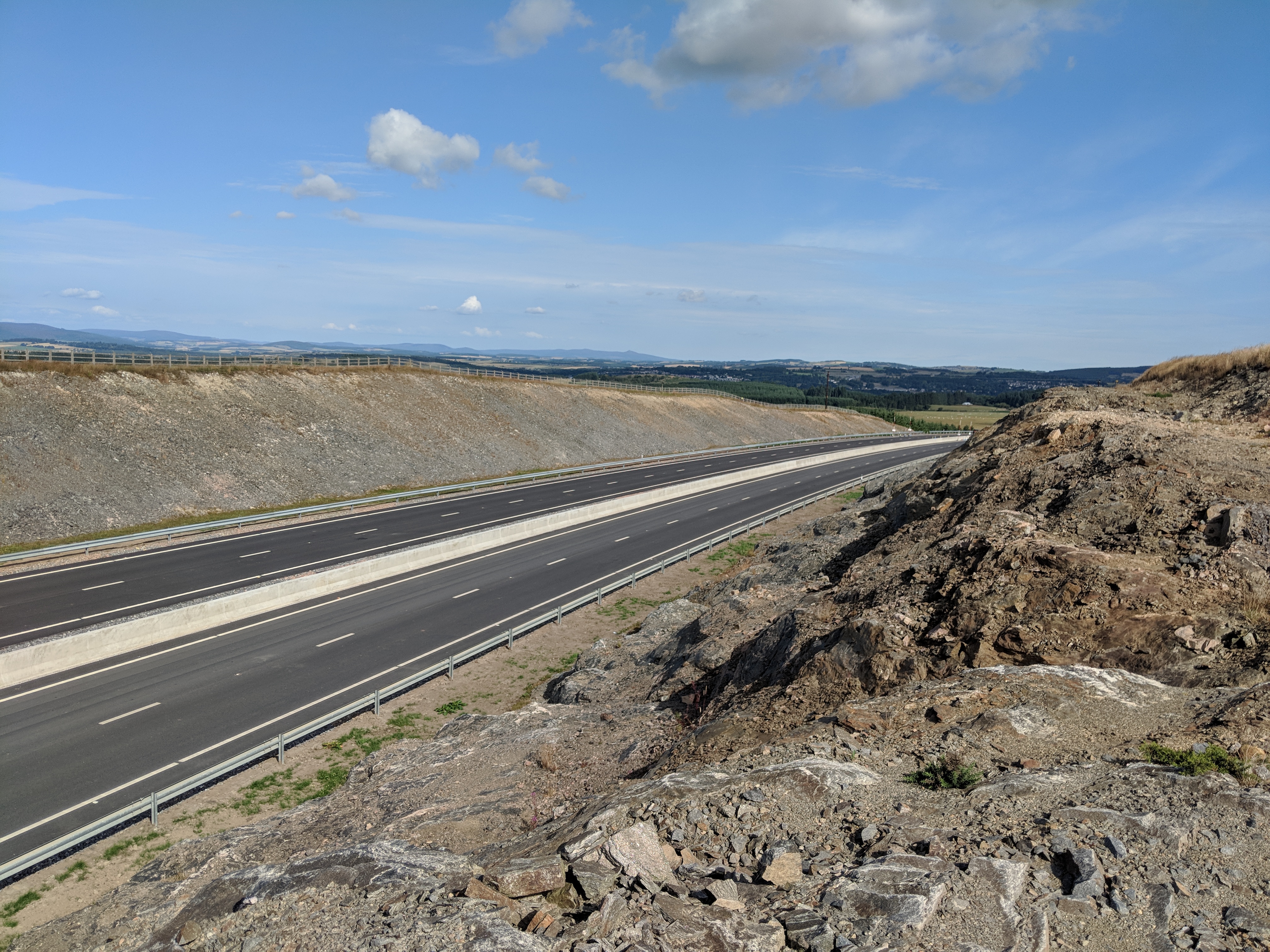
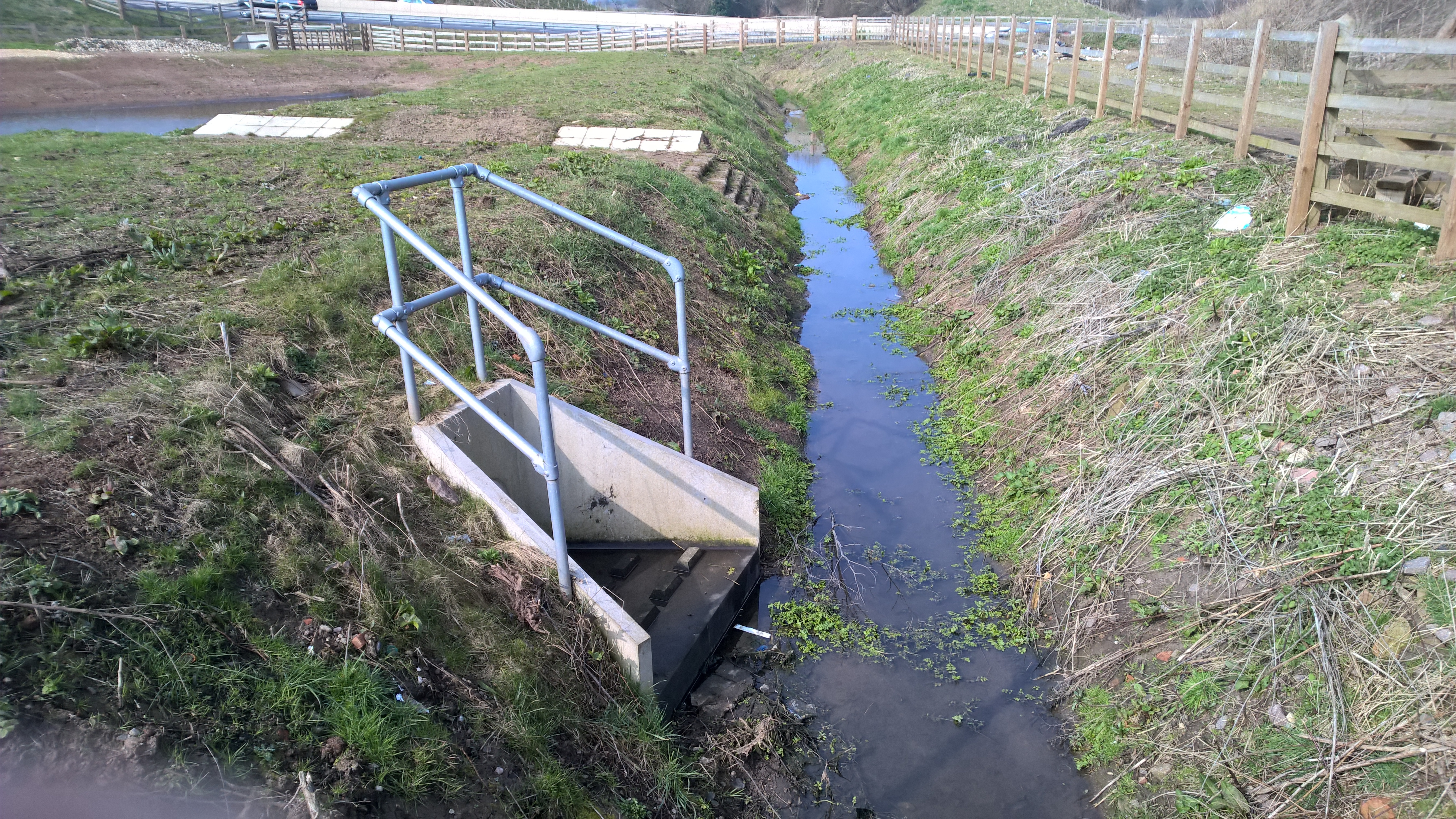
For inspection and maintenance purposes, this part of the asset generally includes embankment slopes, cutting slopes, berms, ditches, crest drainage, toe drainage, revetments and some retaining systems that support the earthworks. On trunk roads and motorways these are usually managed as geotechnical assets. On local roads the exact asset split varies, but the practical inspection issues are much the same.
In simple terms, an embankment is raised fill carrying the road above existing ground. A cutting is ground excavated to take the road through higher land. A batter is the sloping face of either condition. Those faces may be grassed, left in soil, formed in weathered rock or protected with revetment, mesh, gabions or other systems.
Common earthworks defects
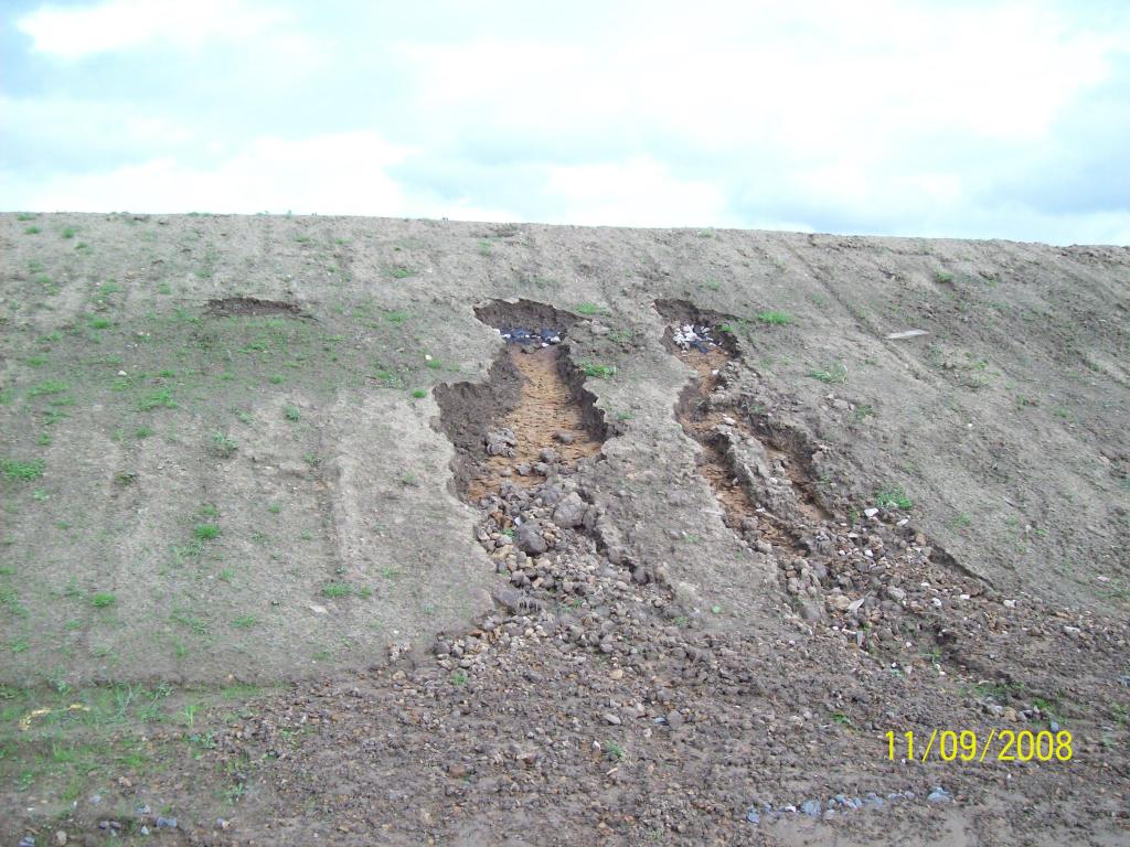
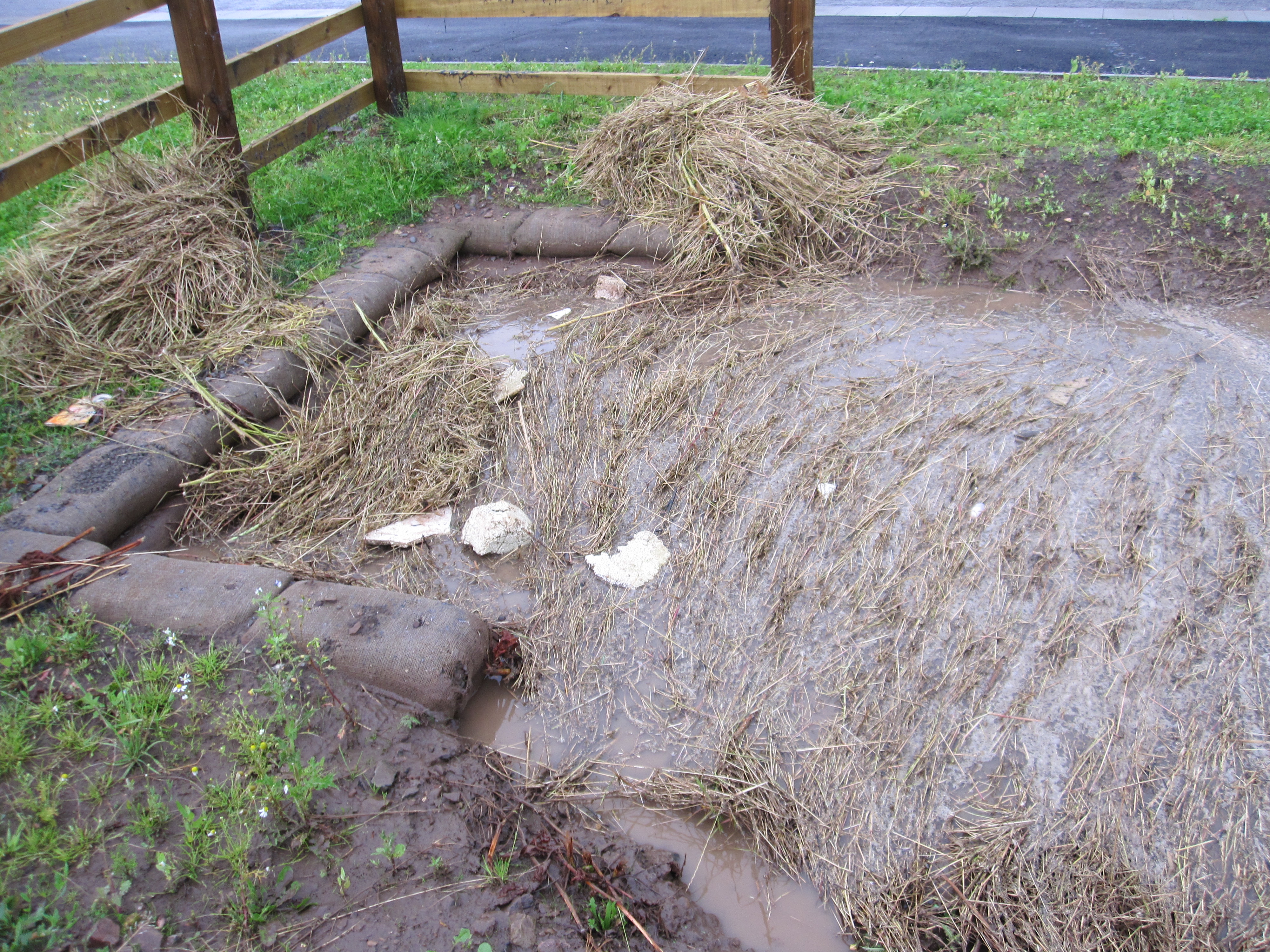
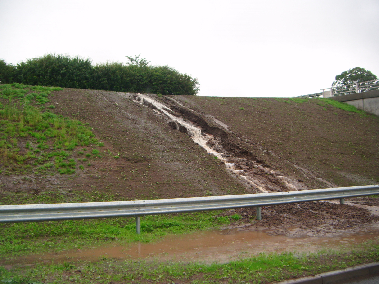
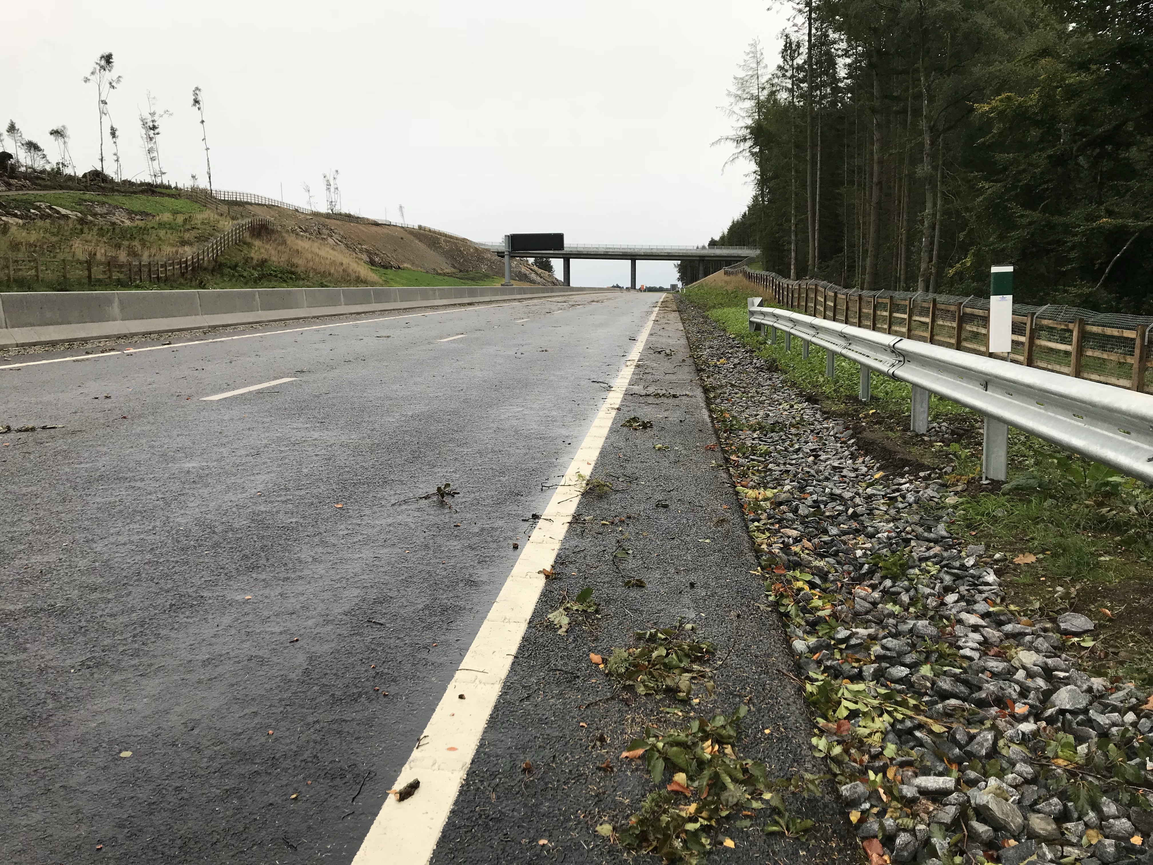
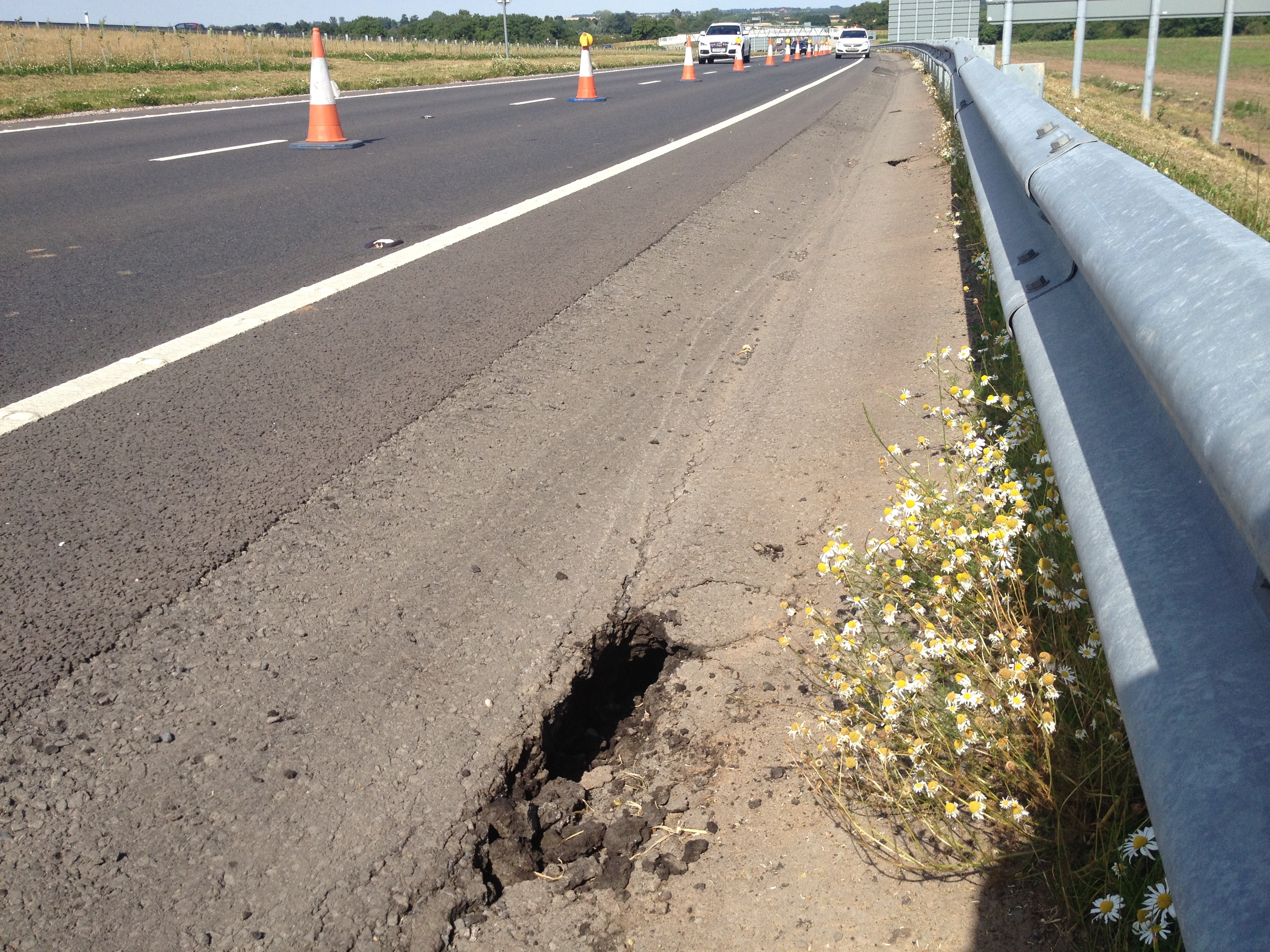
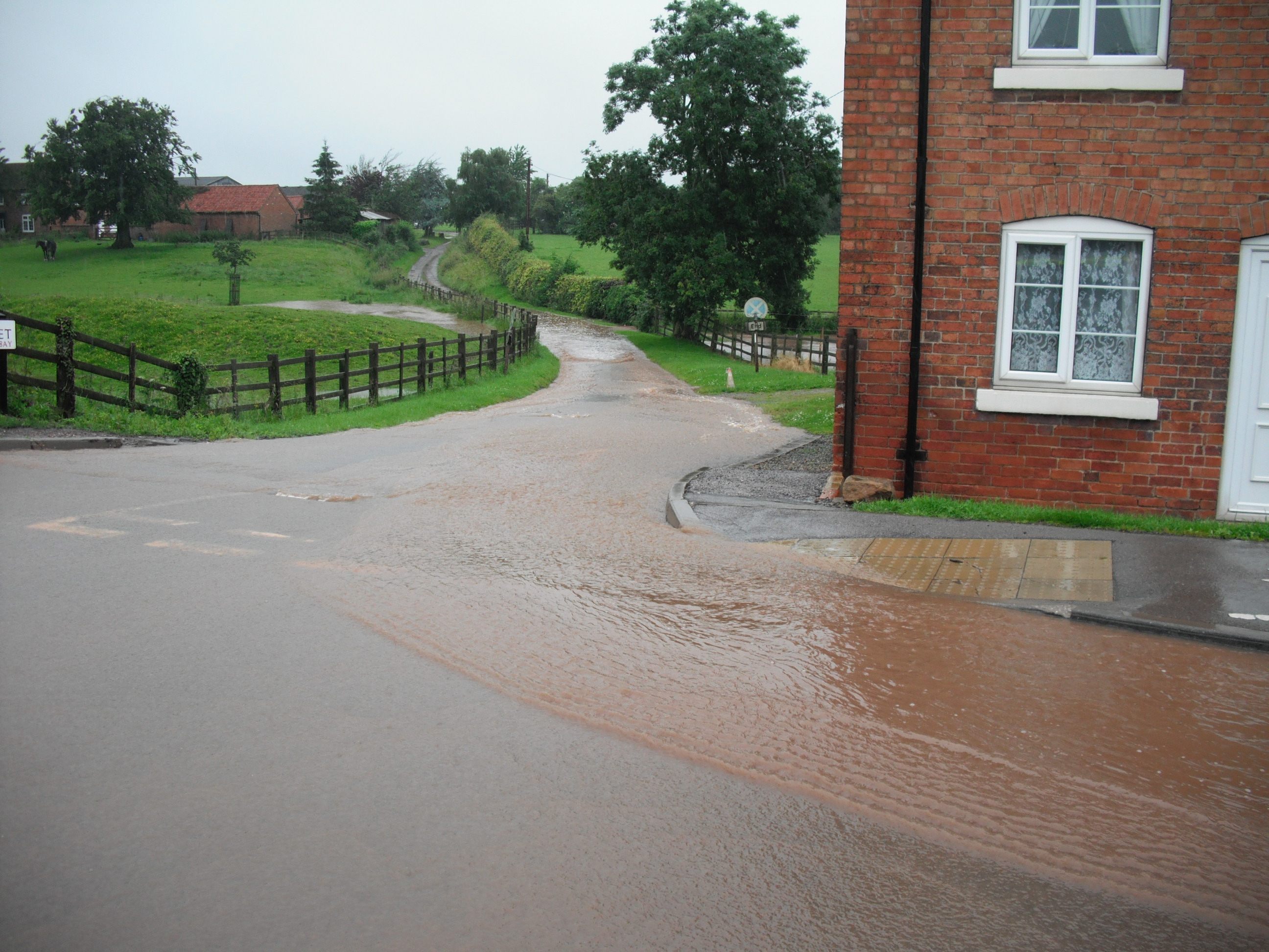
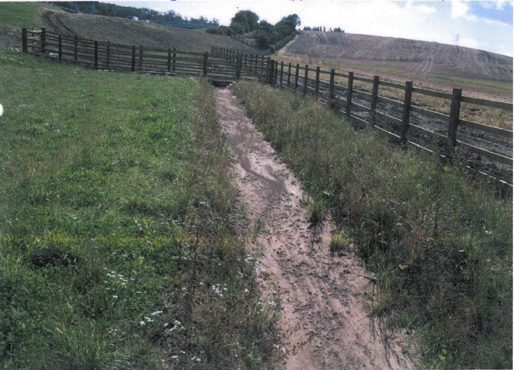
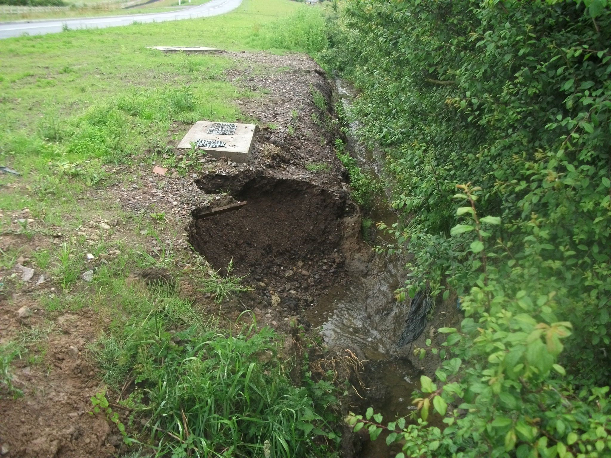
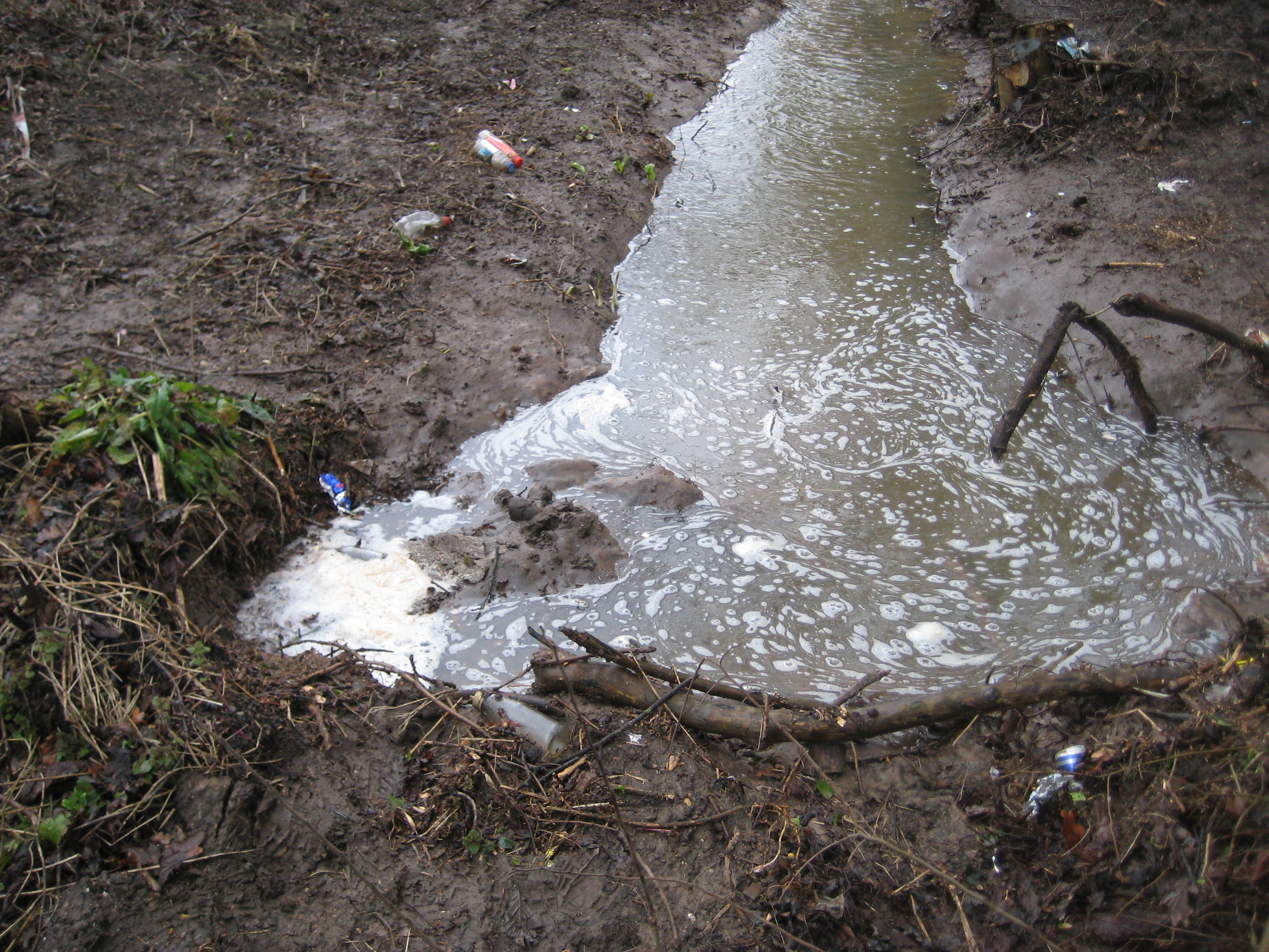
Erosion and washout. This is one of the most common defects. Surface water runs down the slope, strips fines from the face and starts to cut channels into it. On embankments that often begins where vegetation has been lost or never established properly. On cuttings it often appears where runoff is concentrated or drainage is poor. Left alone, erosion can steepen the face locally, expose weaker material and undermine outfalls, channels or service crossings.
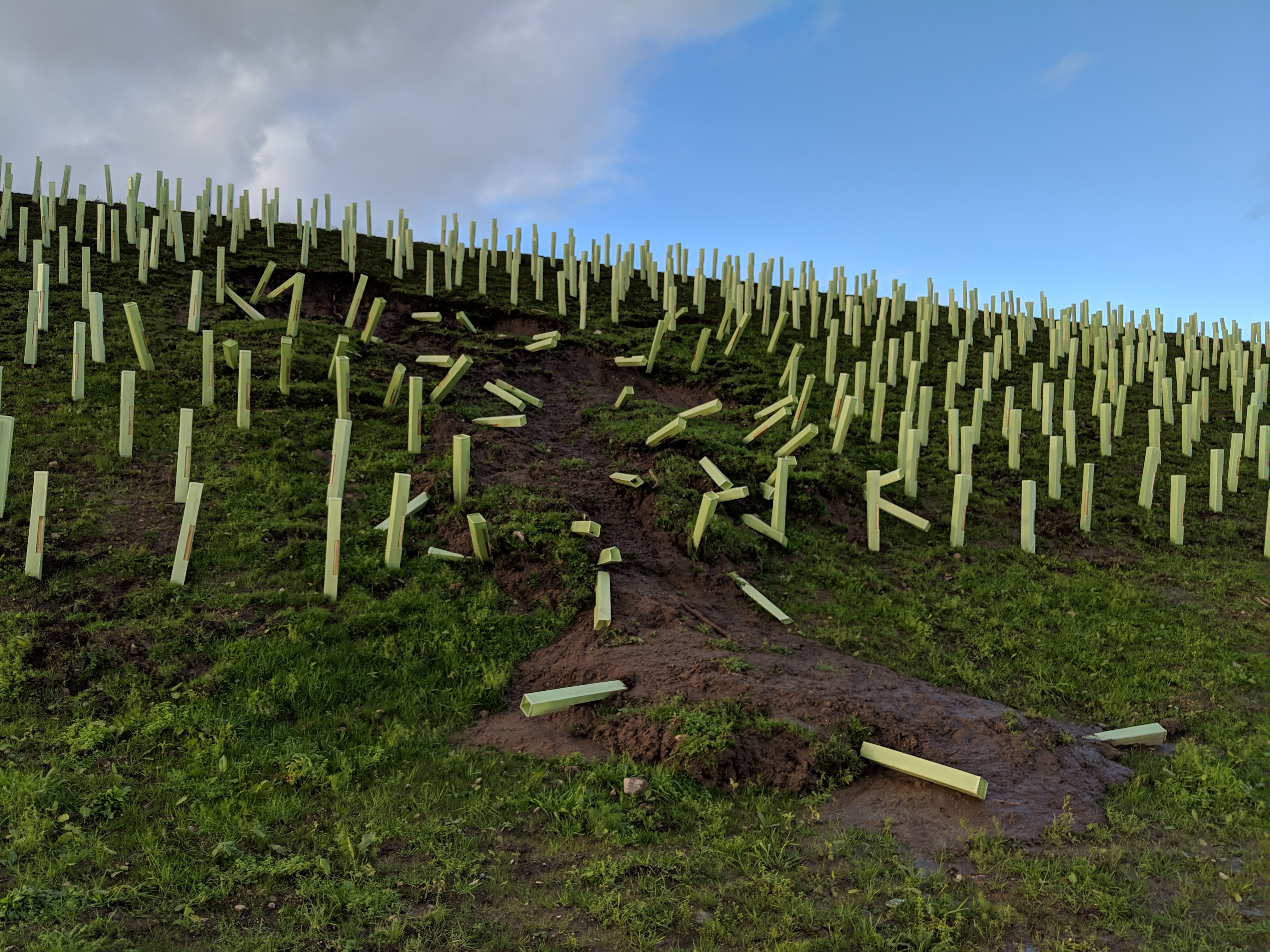
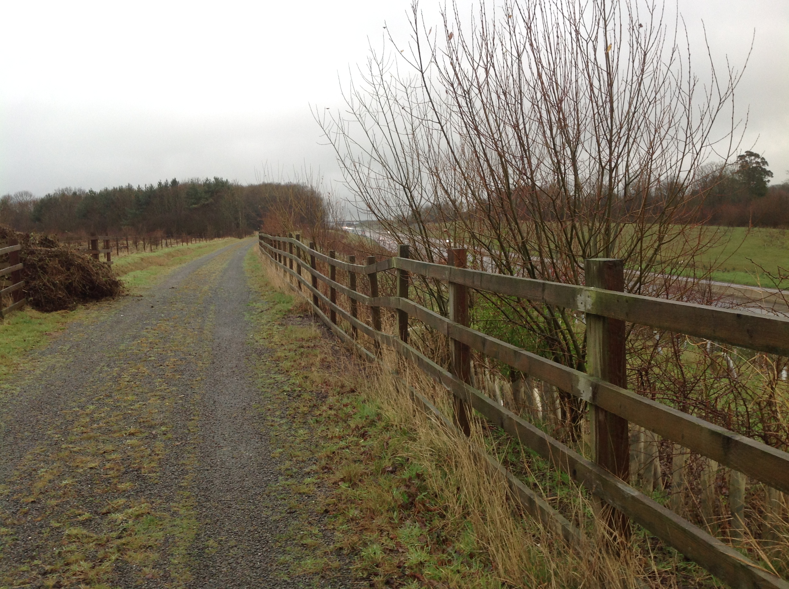
Slips and local failures. A slip is movement of soil or fill down the slope. Failures can be shallow and near-surface, or deeper and more serious. Common triggers are prolonged rainfall, rising pore water pressures, poor drainage, loss of toe support, over-steepening, weak layers within the slope or loading near the crest. Fresh scarps, hummocky ground, displaced fencing, leaning posts and debris at the toe are all warning signs.
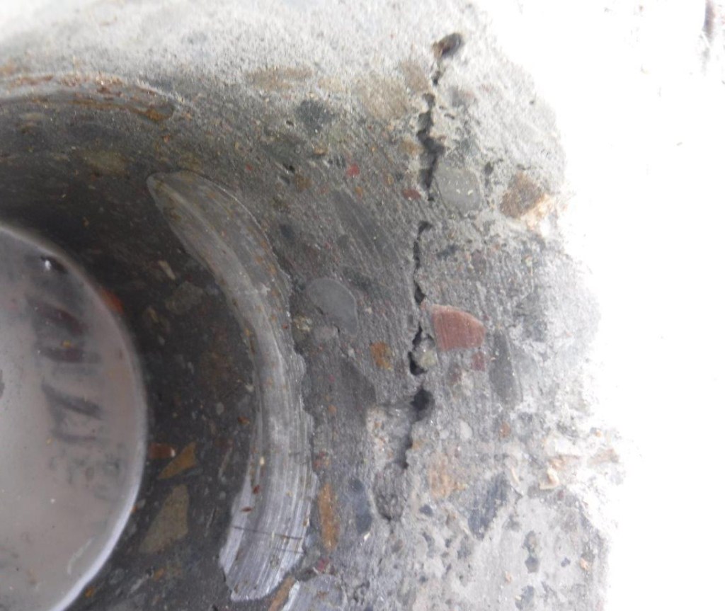
Tension cracks and cracking. Not every crack means the slope is failing, but a crack running parallel to the crest is one of the classic warning signs of instability. It can indicate that the upper part of the slope is starting to pull away from the more stable ground behind. Cracking can also appear from shrinkage, desiccation, settlement or freeze thaw action, so context matters. The concern increases where cracks are opening up, extending, holding water or appearing with other signs of movement.
Bulging, slumping and creep. These are all signs that the slope may be deforming, even if it has not yet failed. A toe bulge, terraced surface, bowed fence line or progressive downward movement of the face can point to softening, saturation, poor compaction, weak foundation material or long-term creep in cohesive fills. These conditions are useful early warnings because they often show up before a larger slip develops.
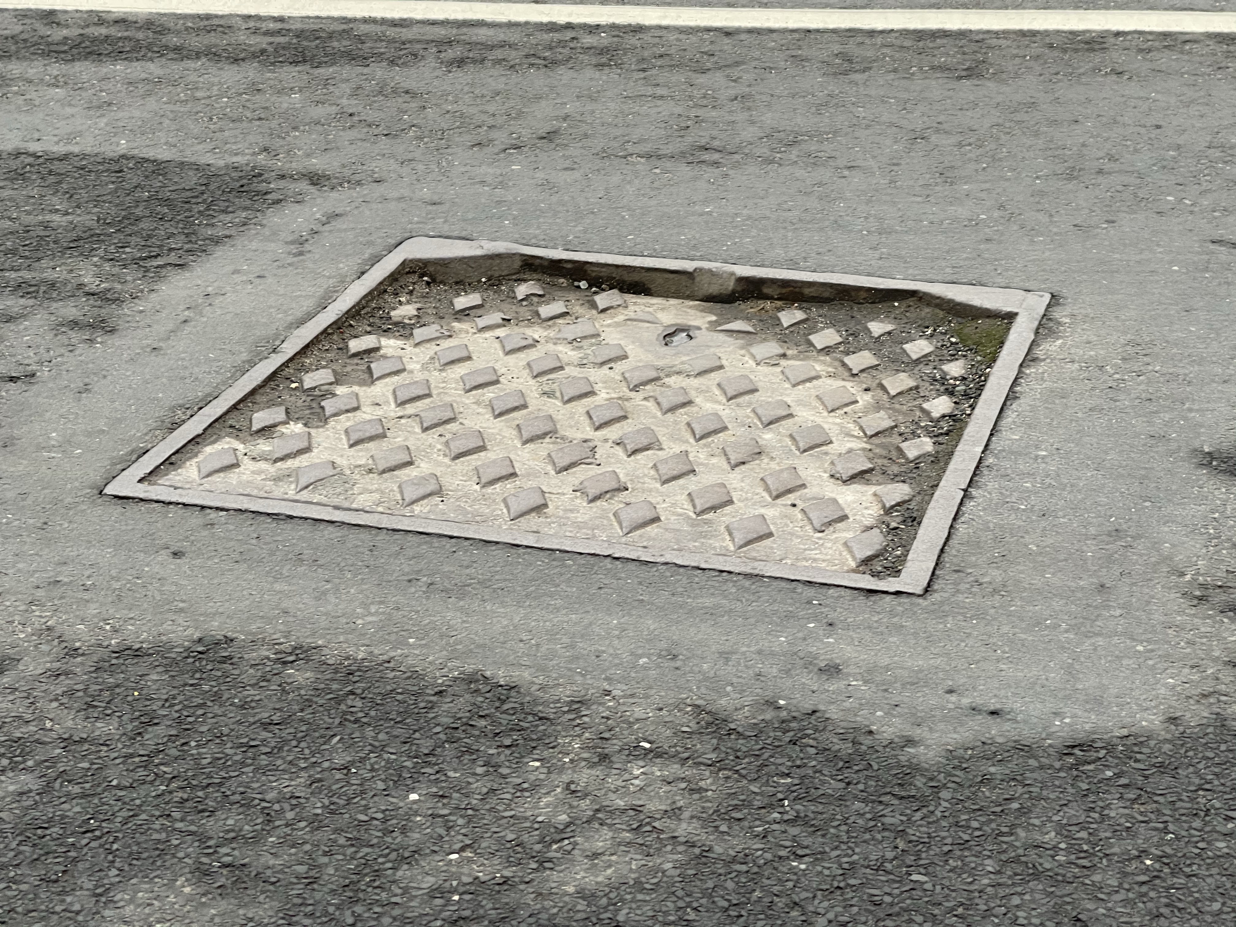
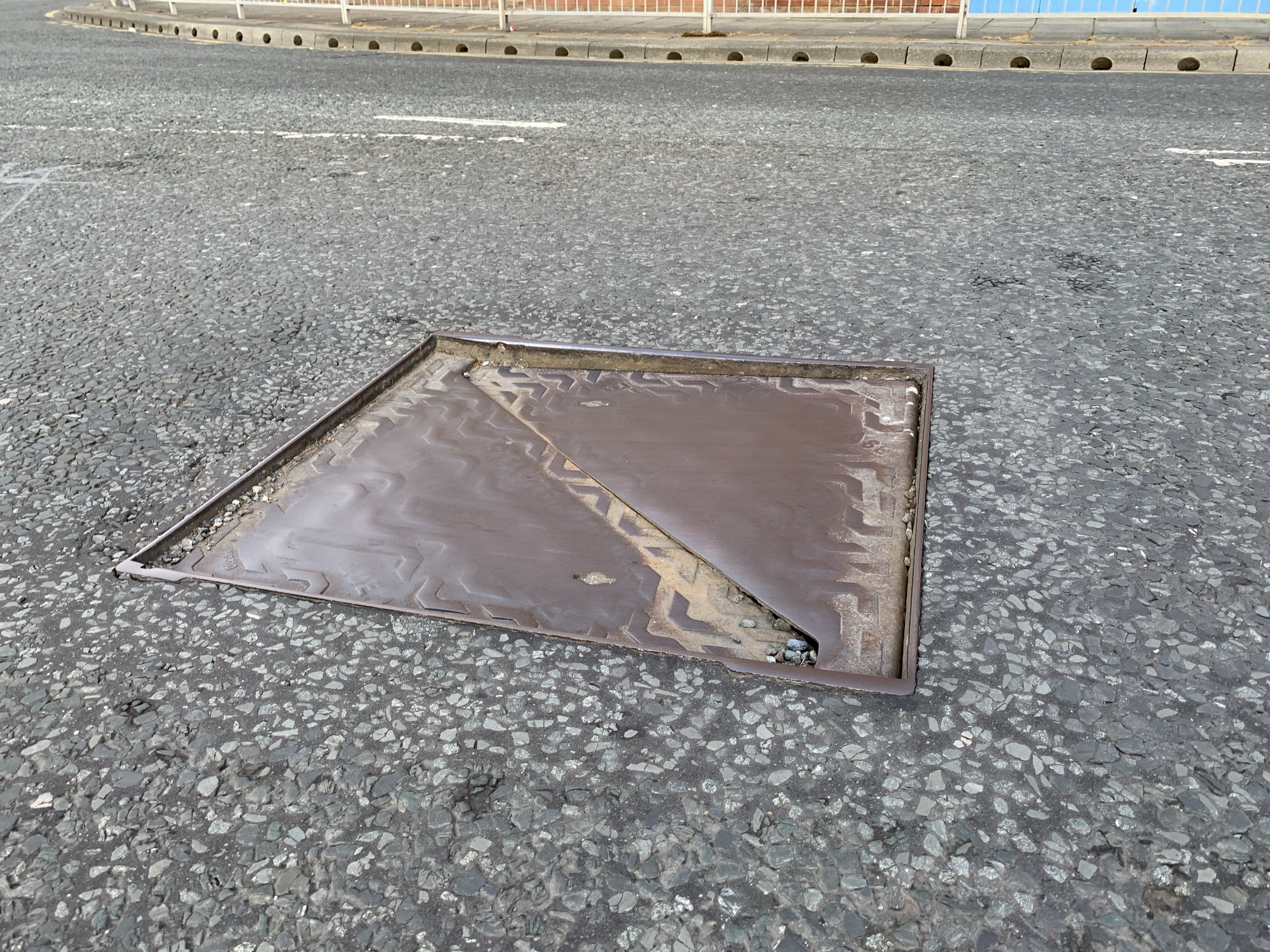
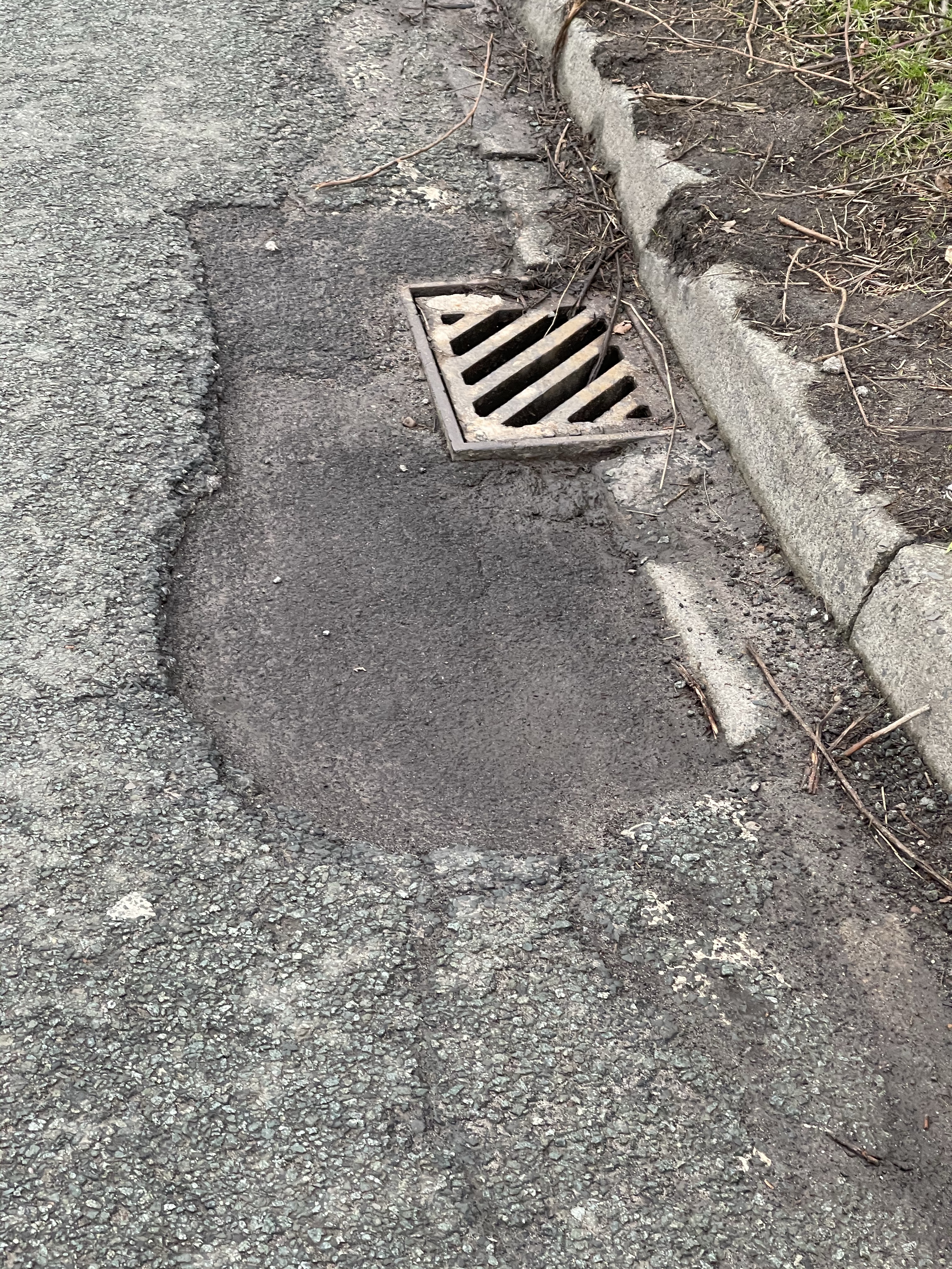
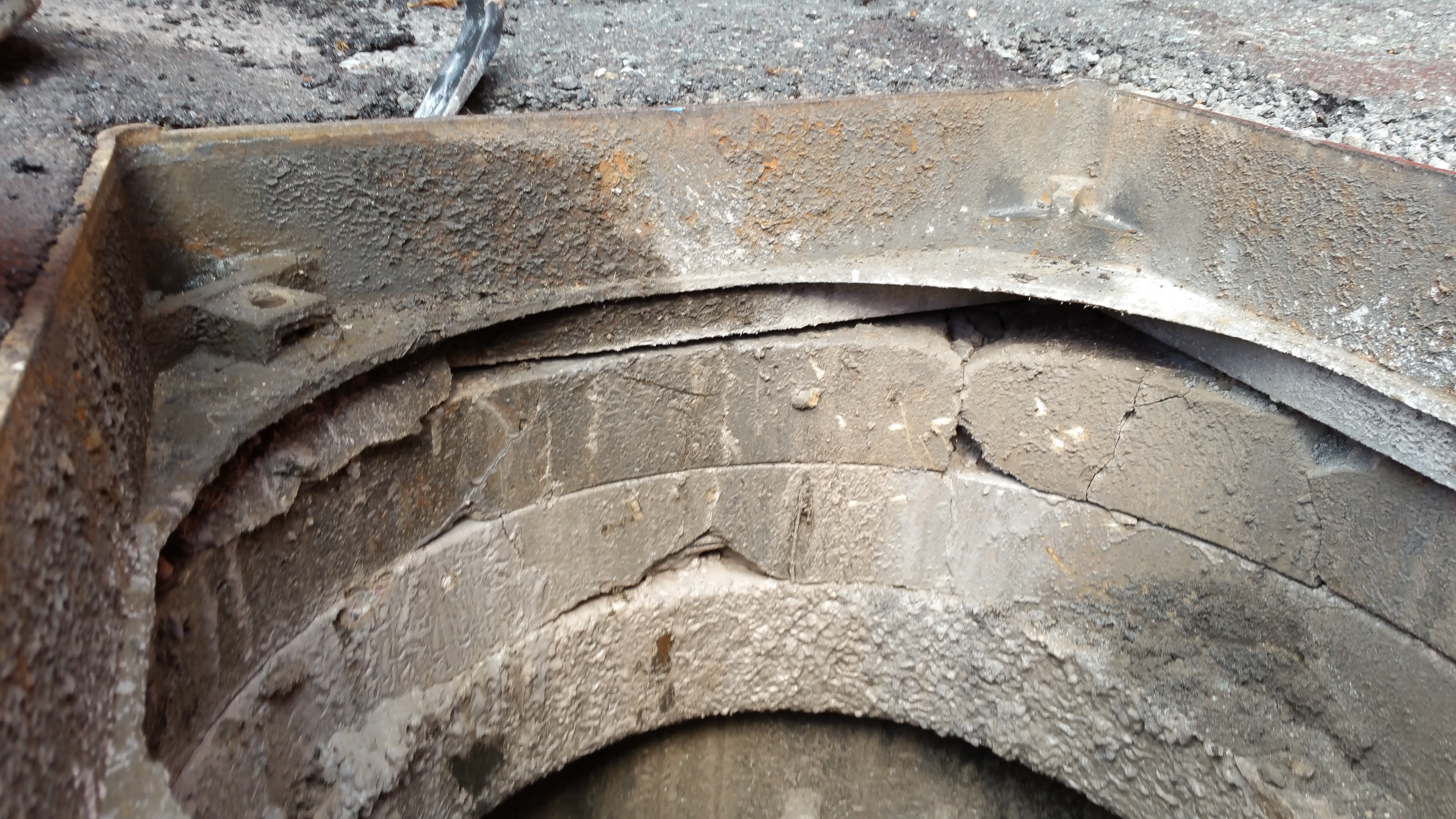
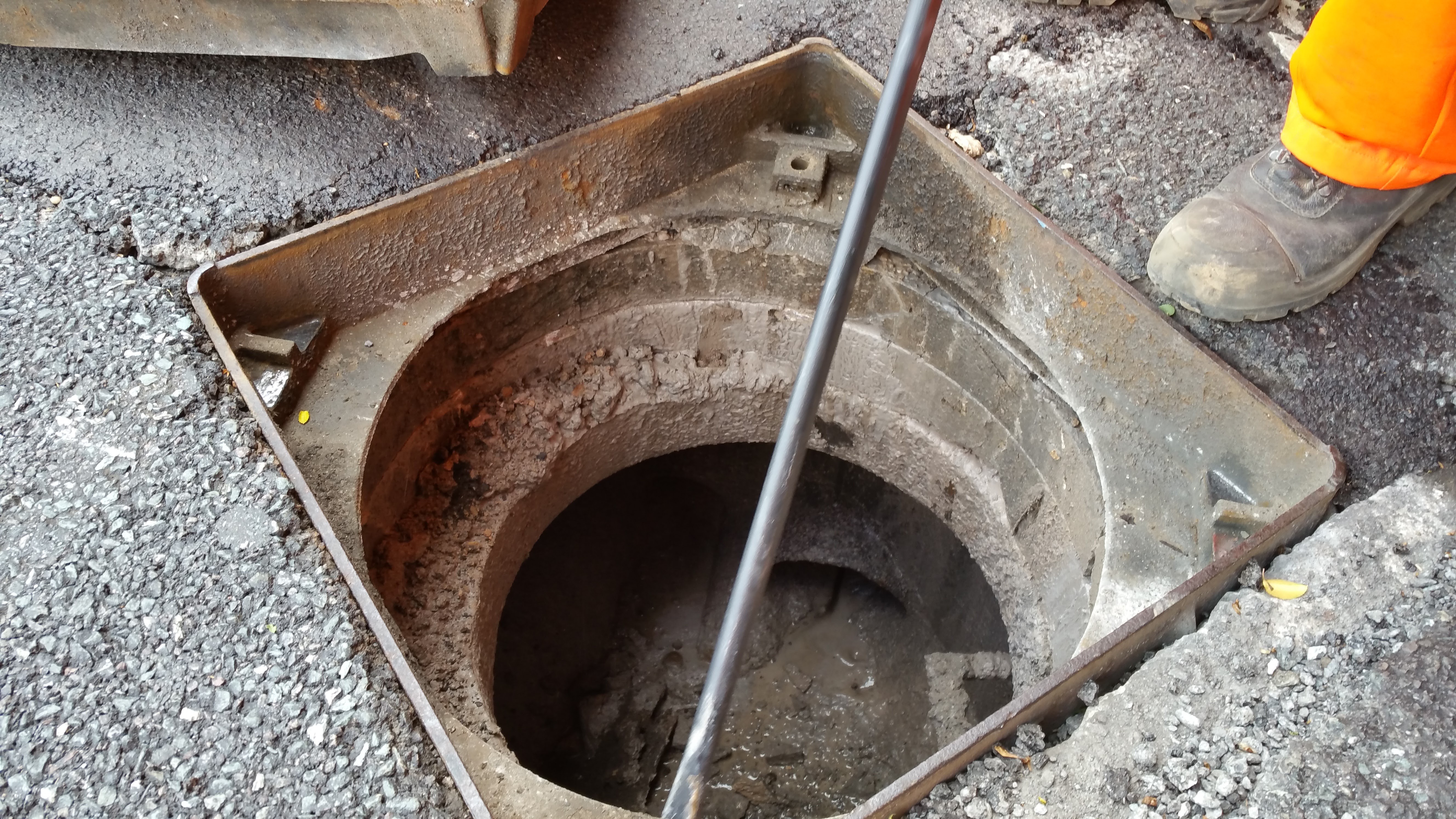
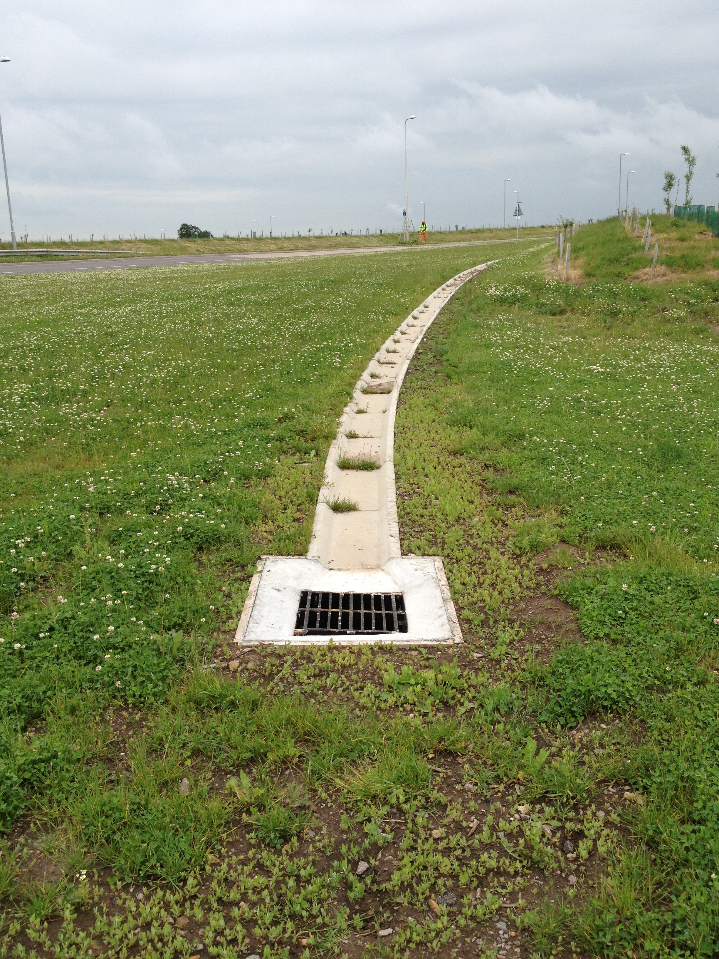
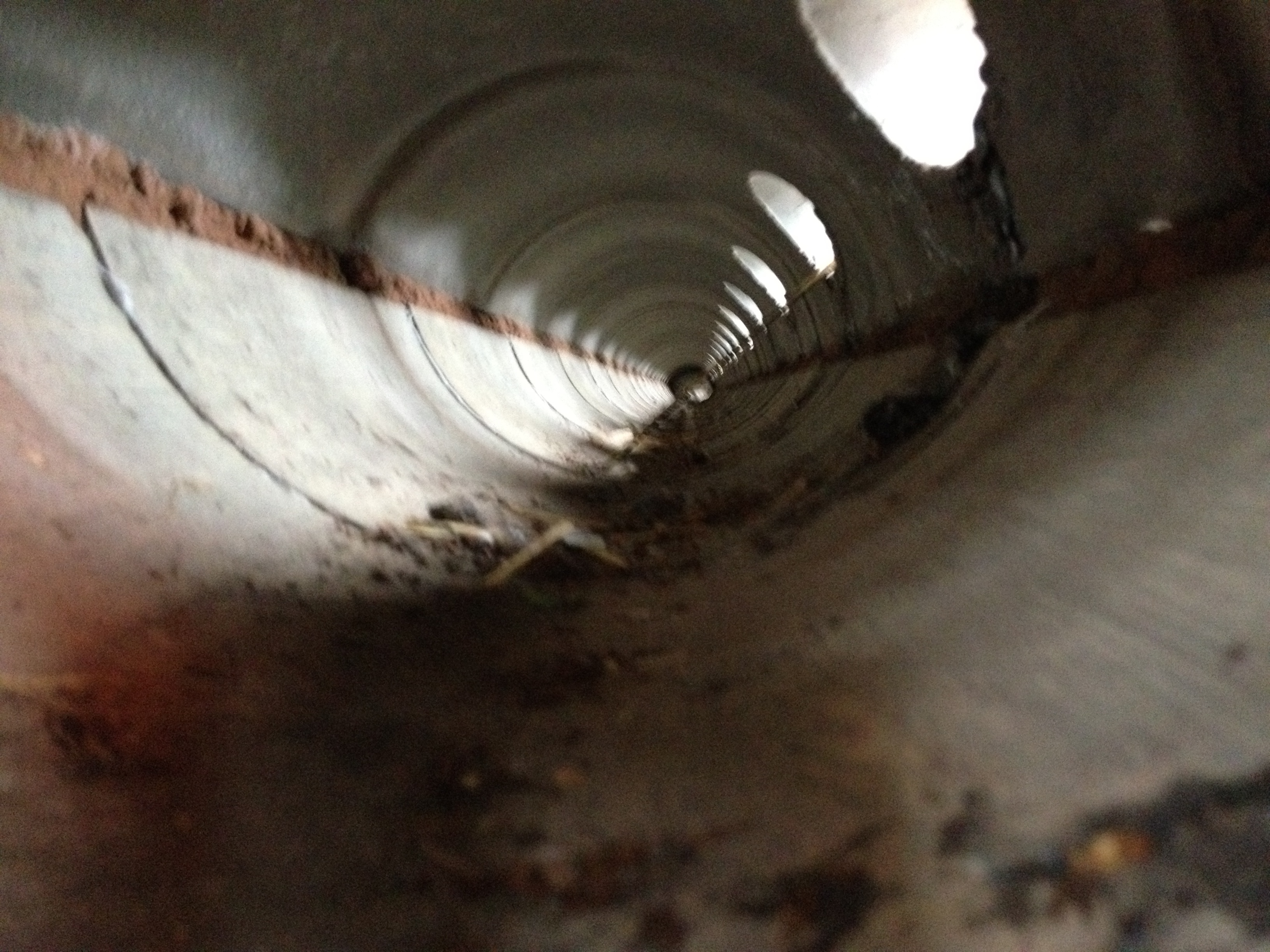
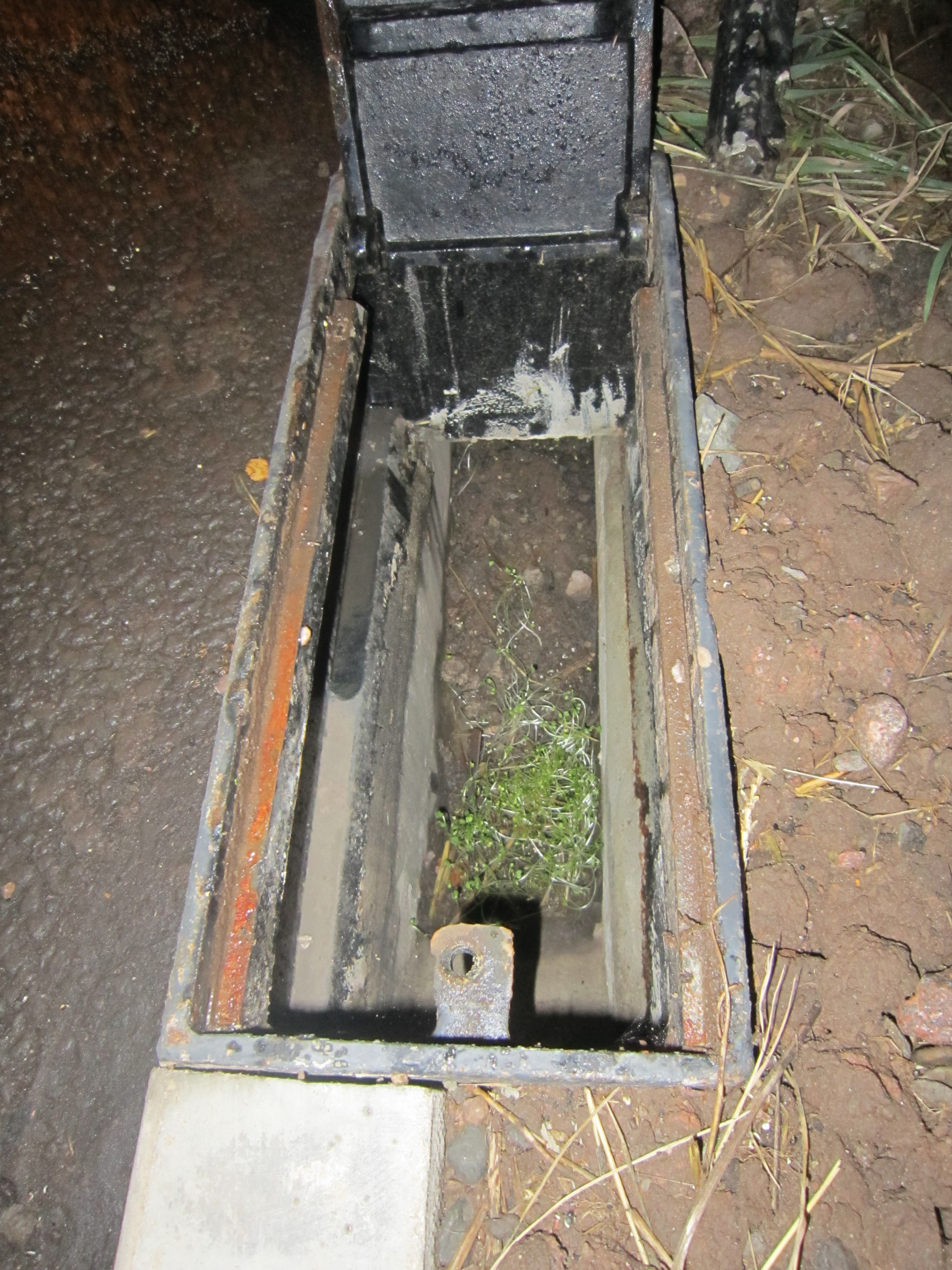
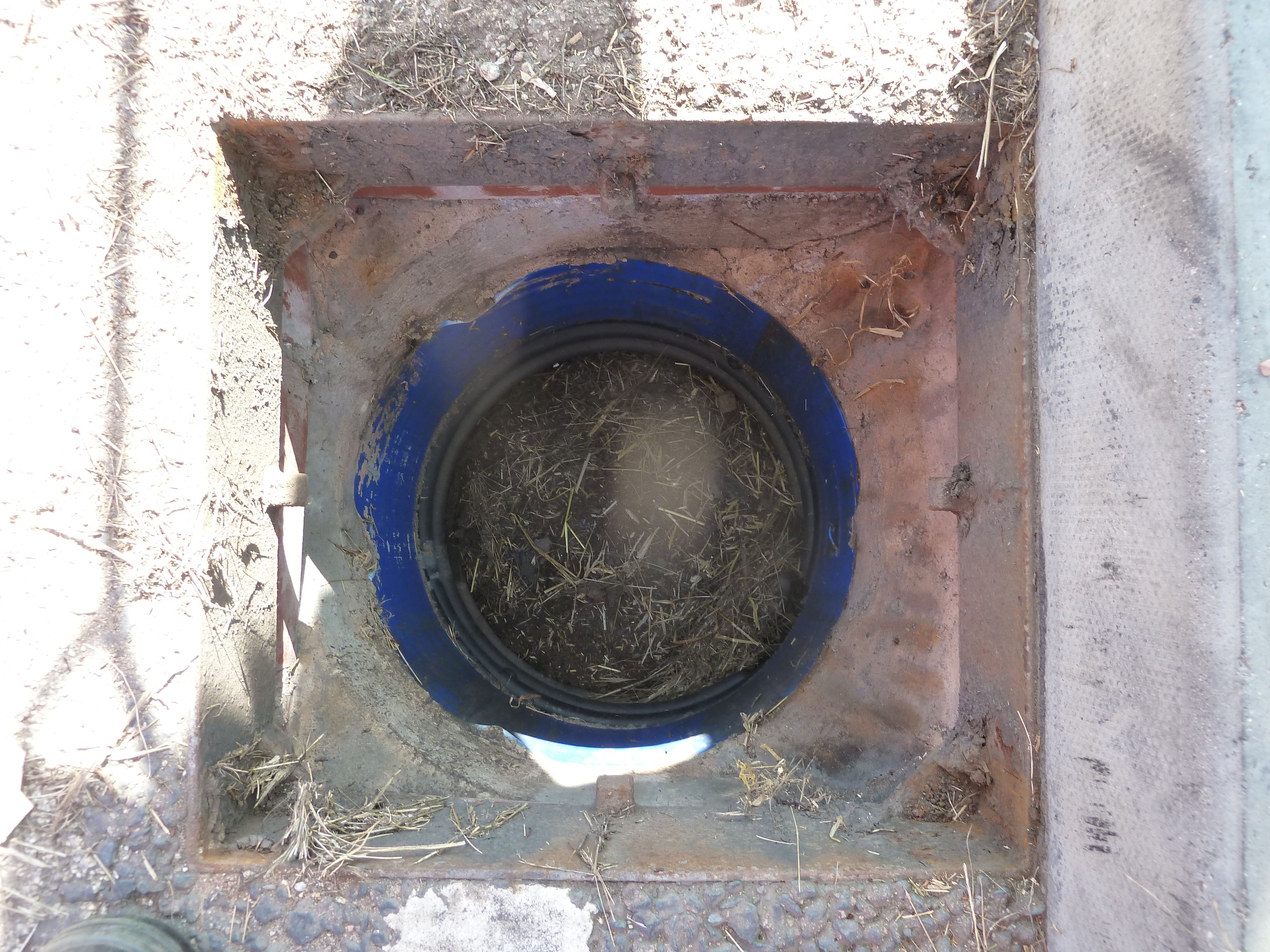
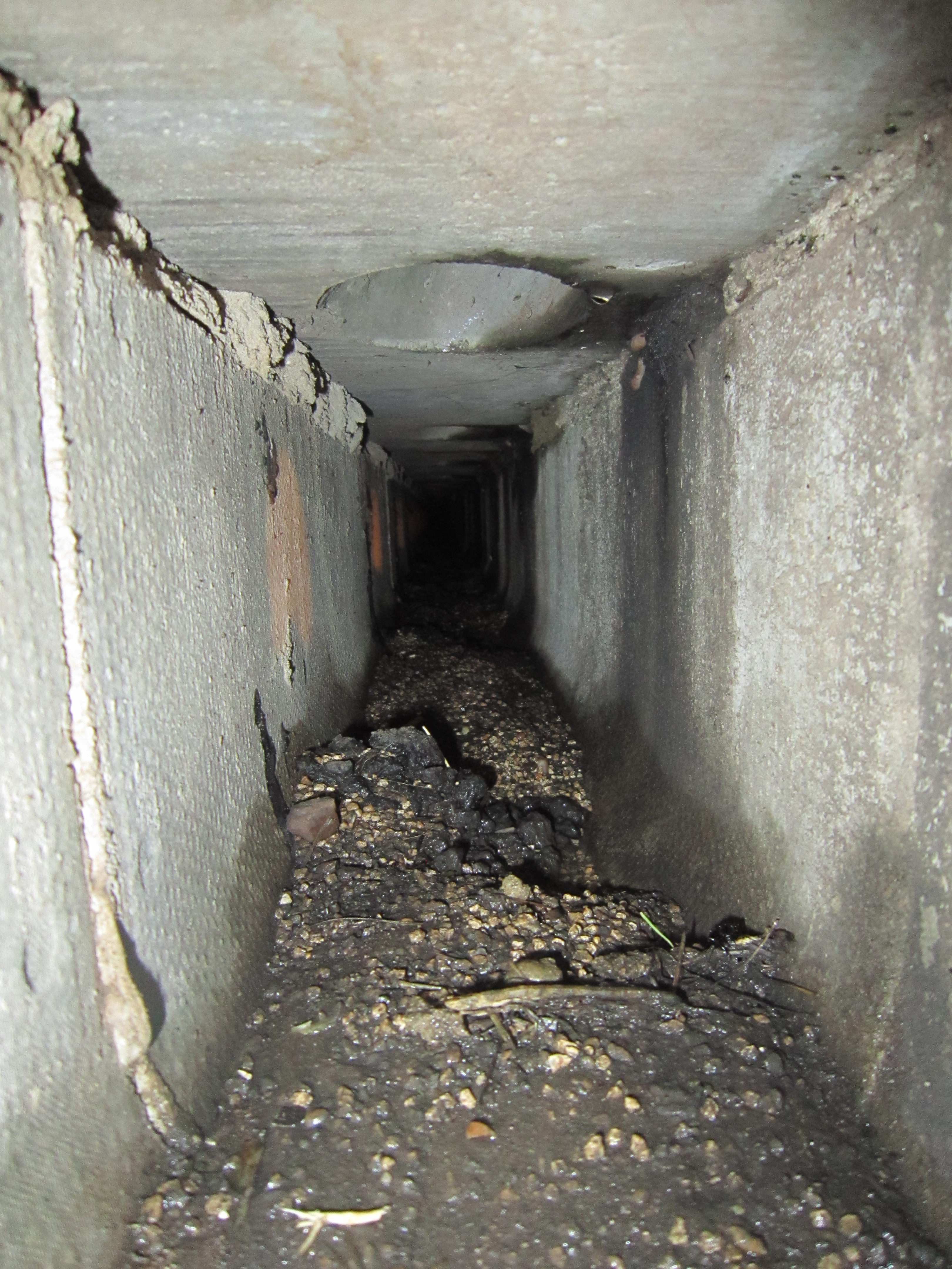
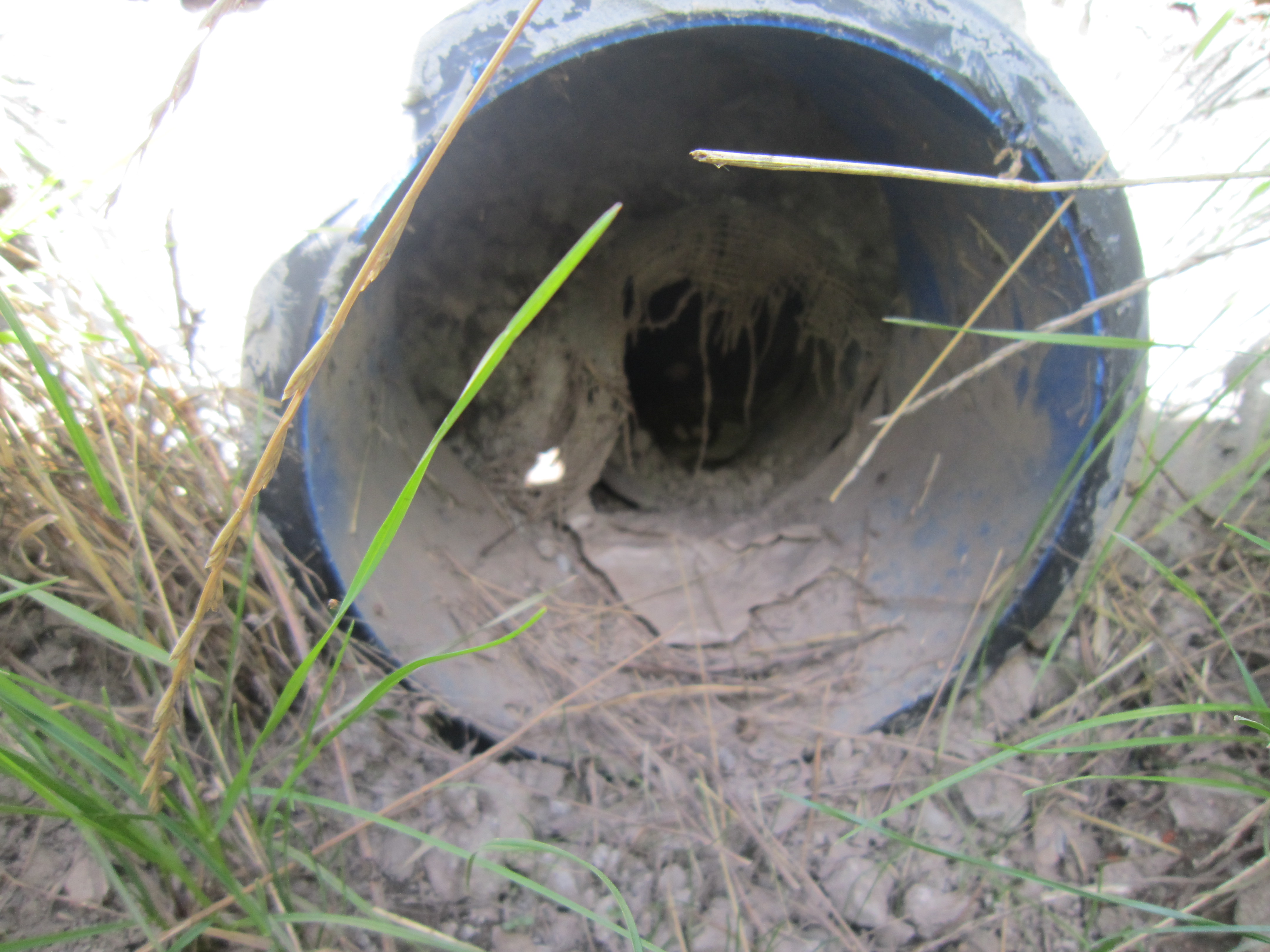
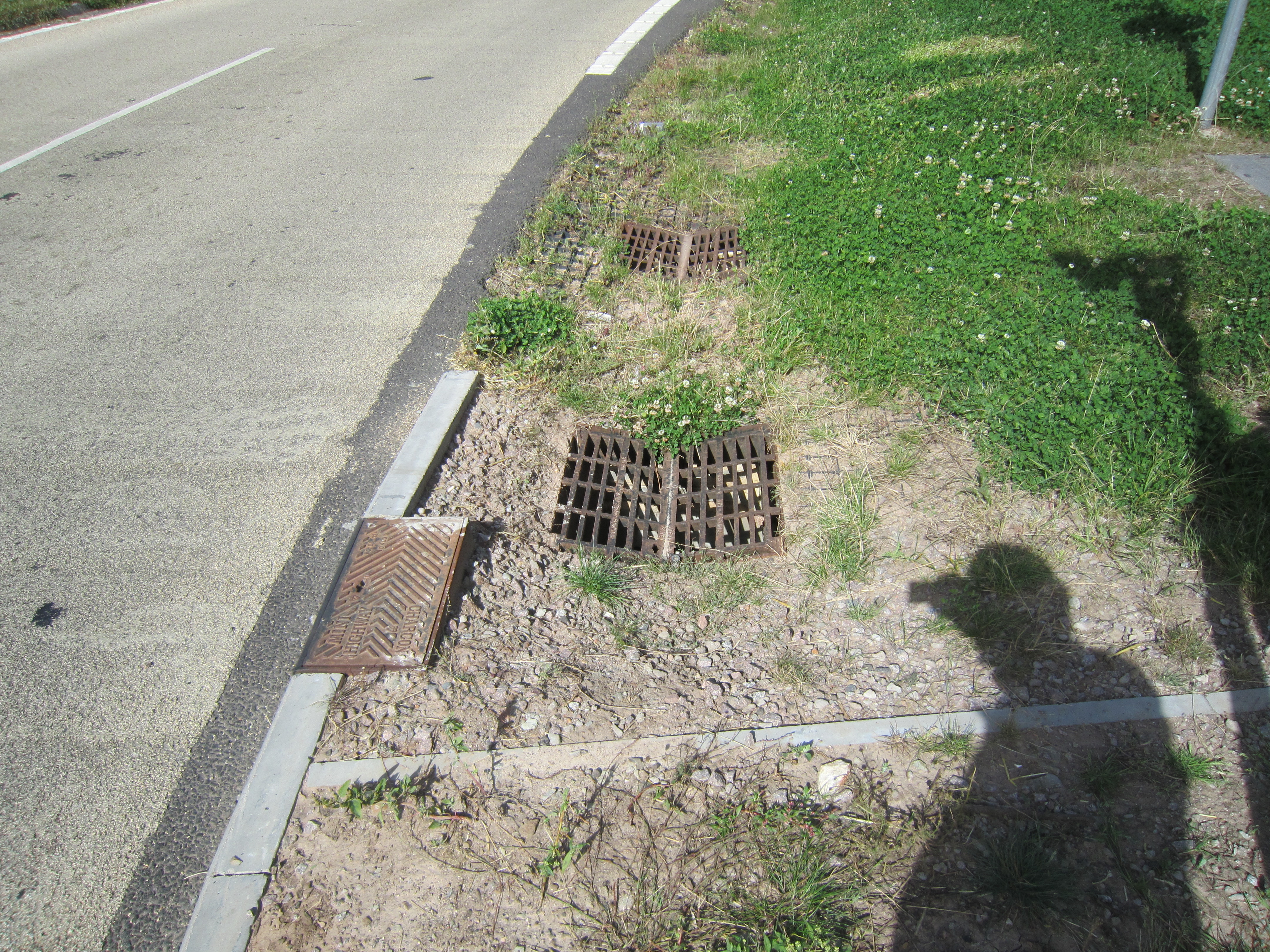
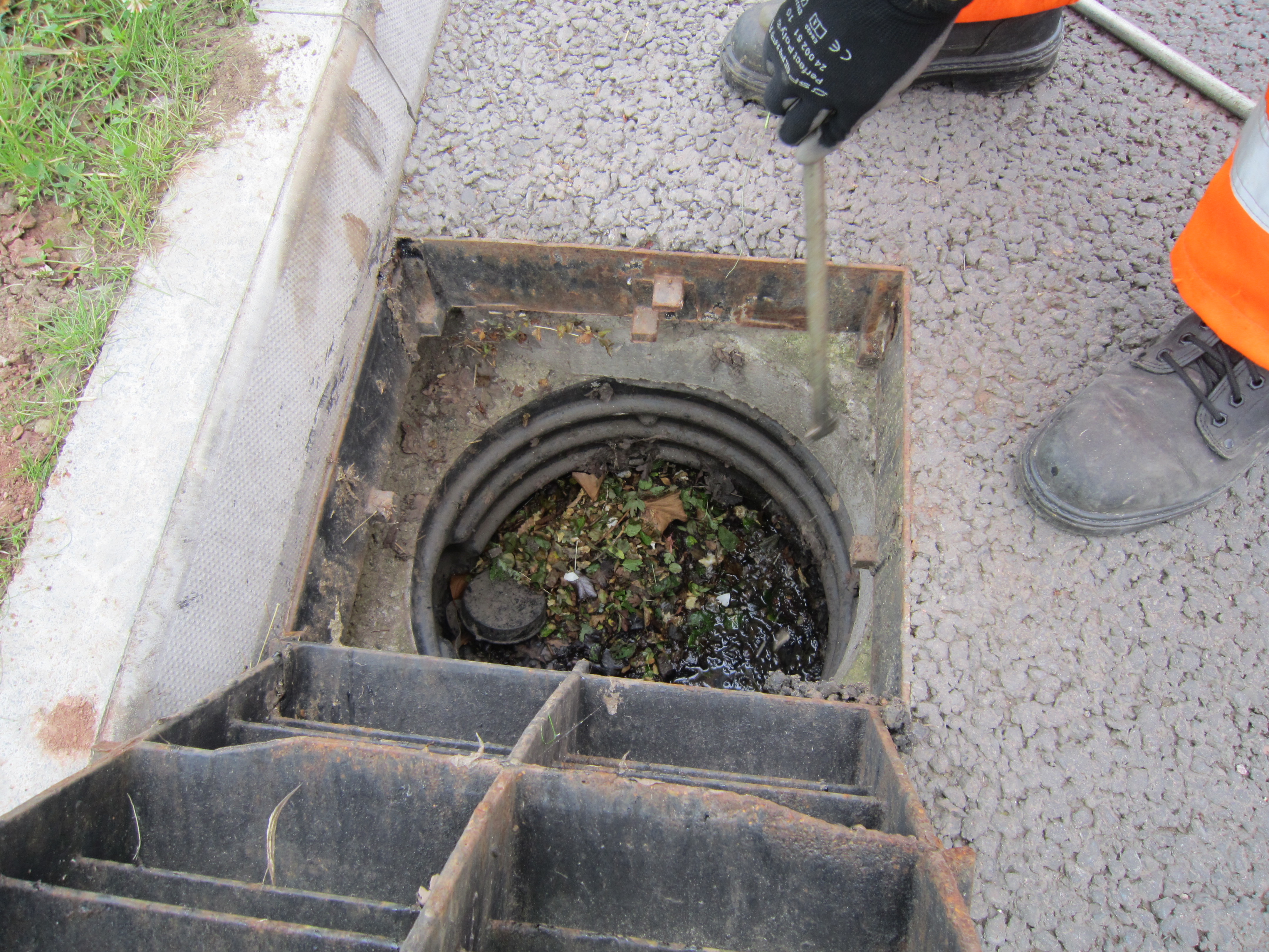
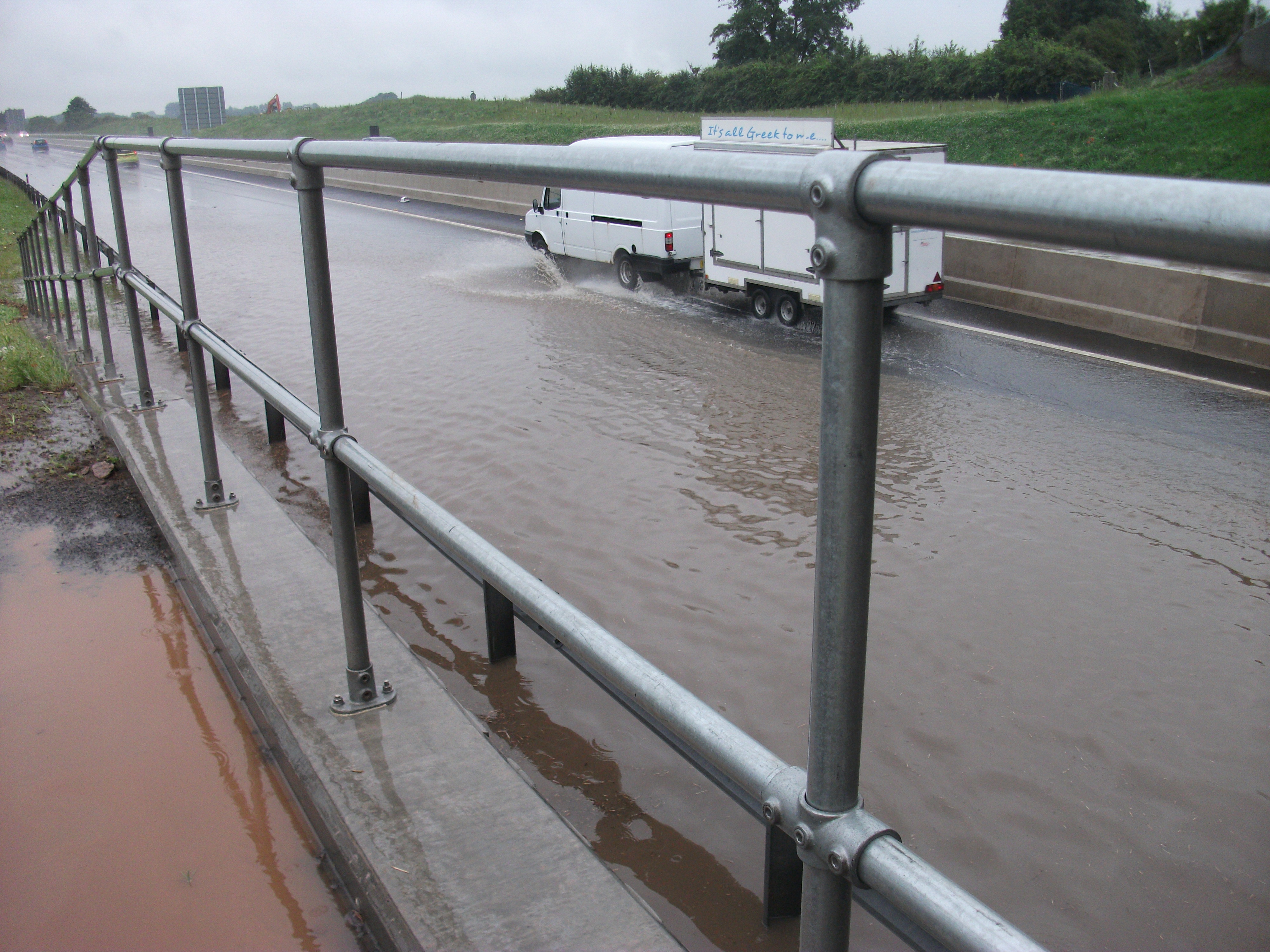
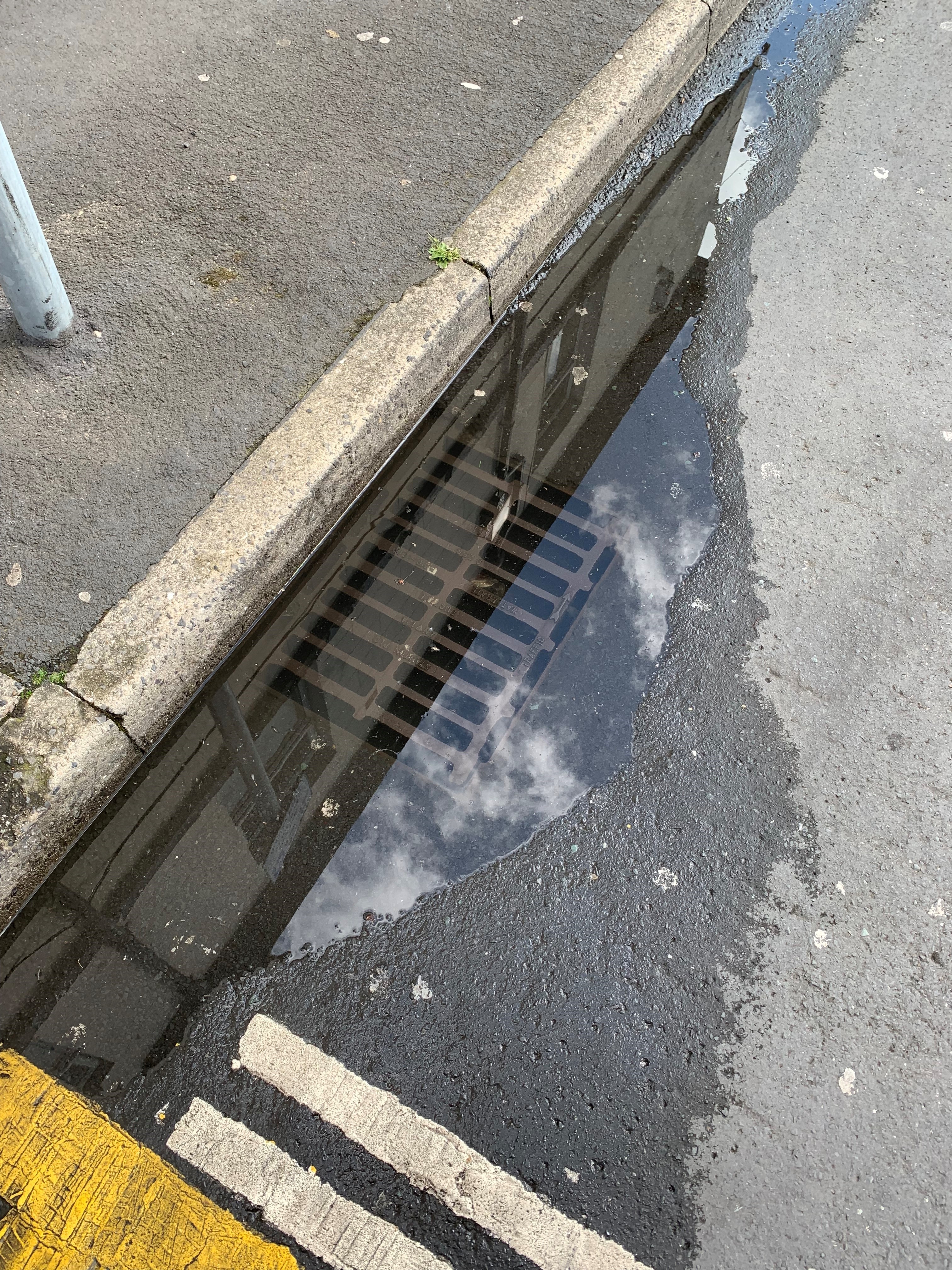
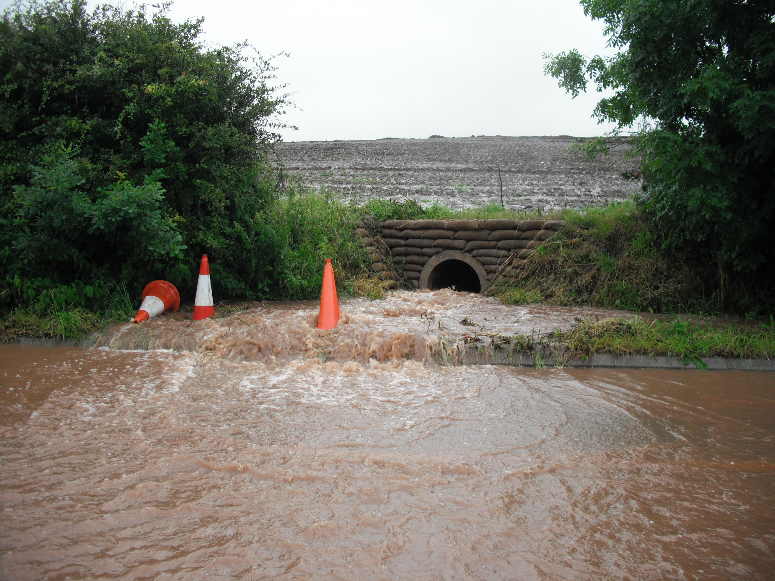
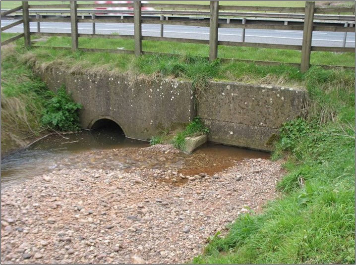
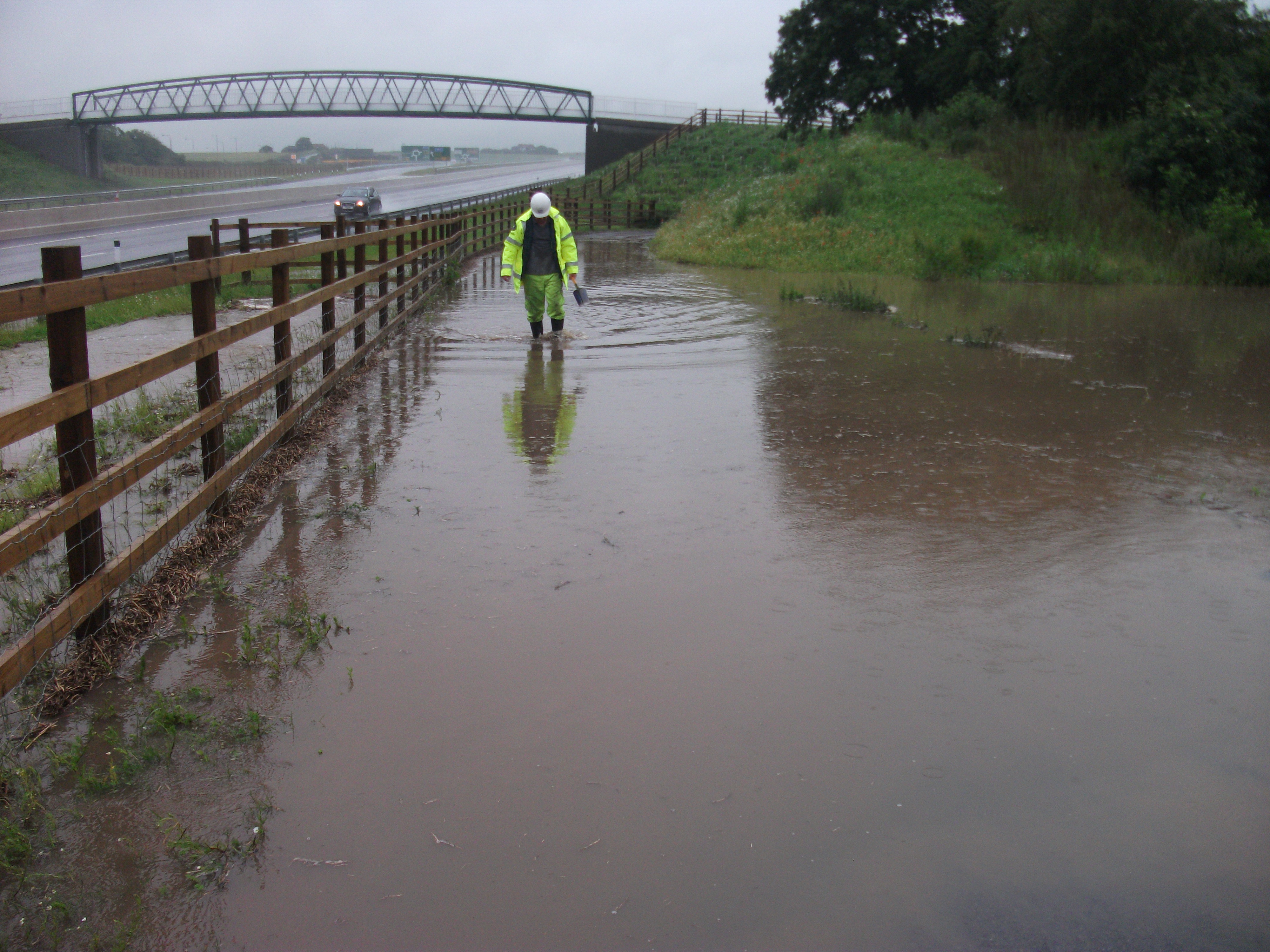
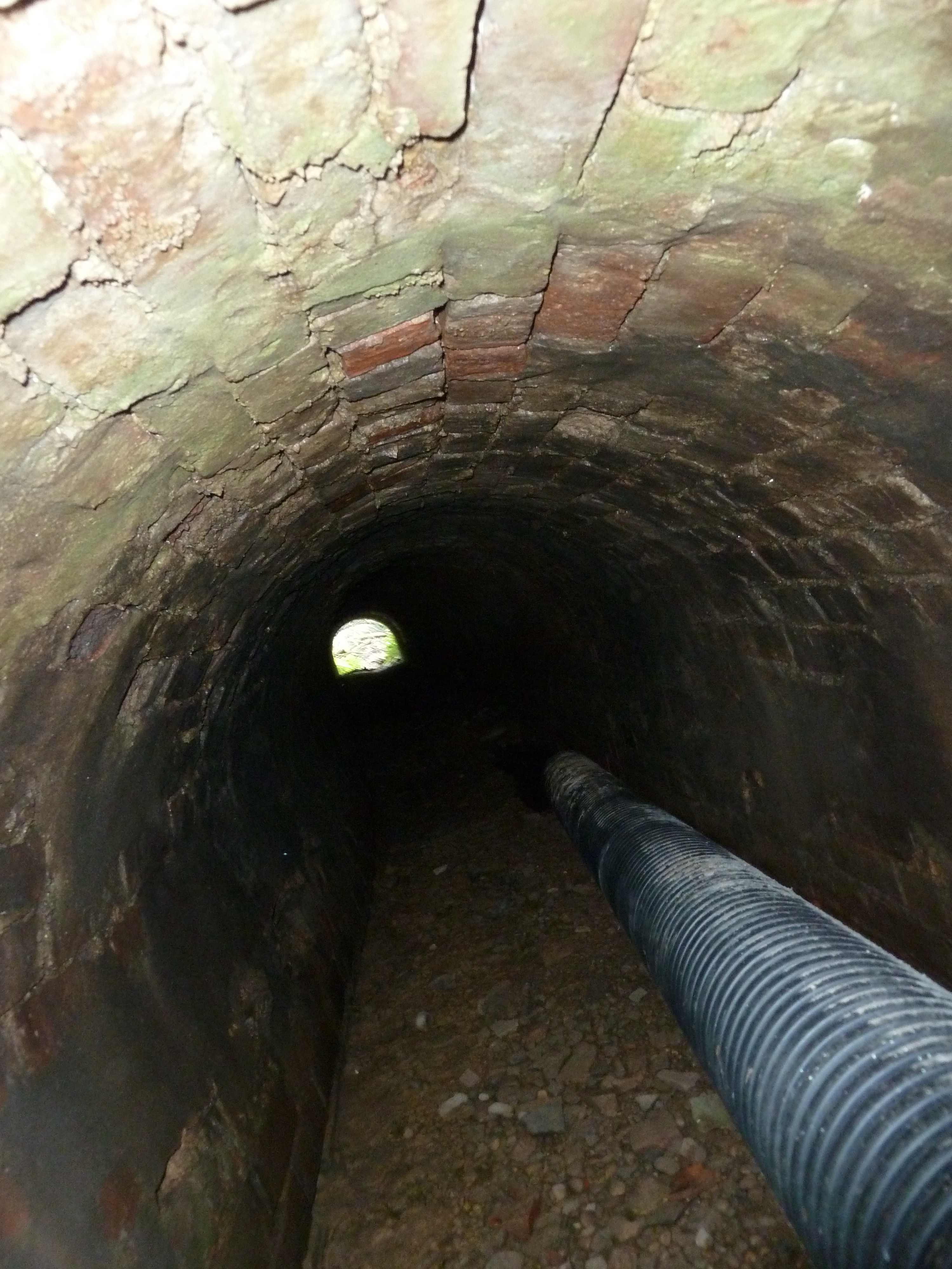
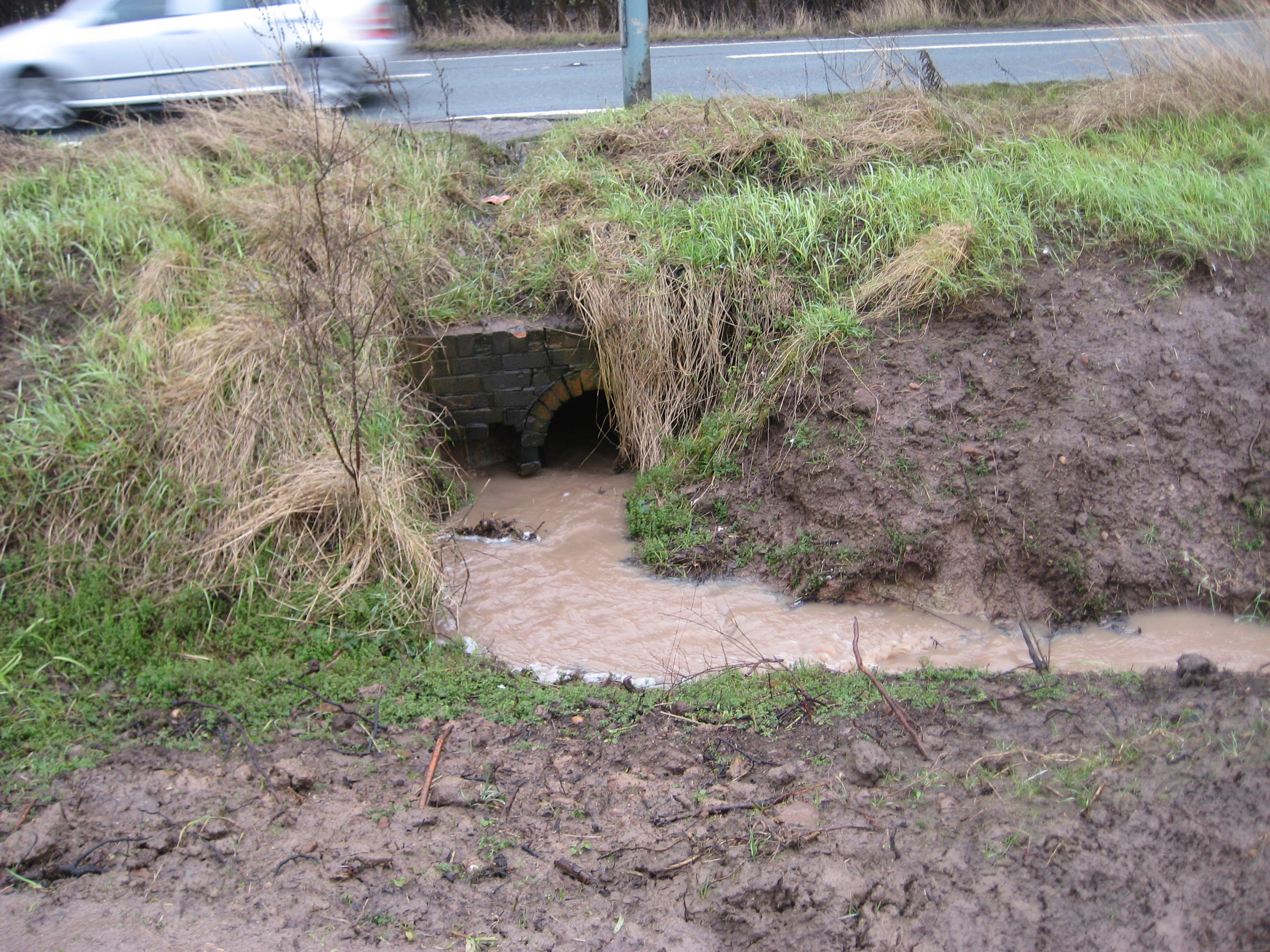
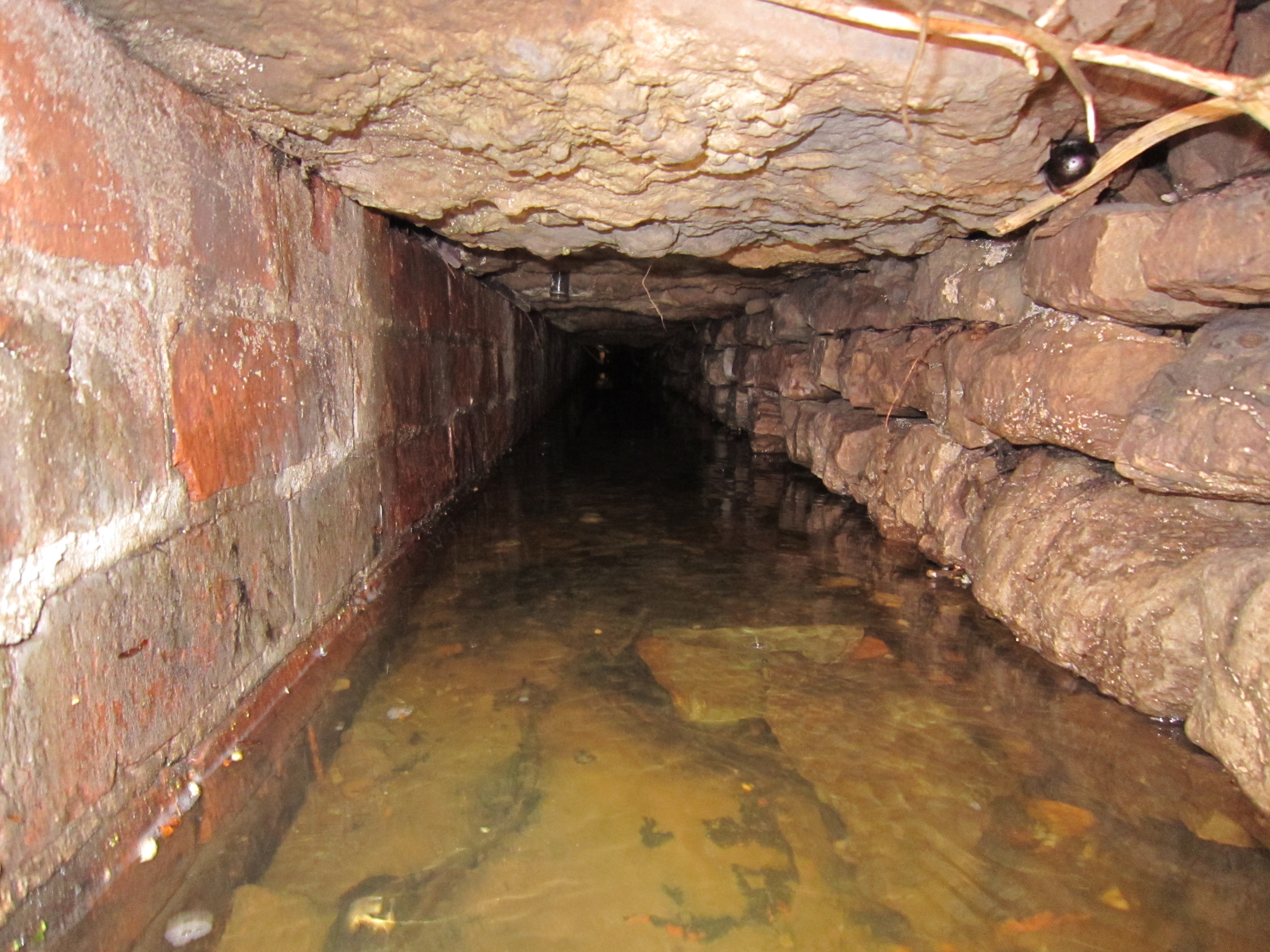
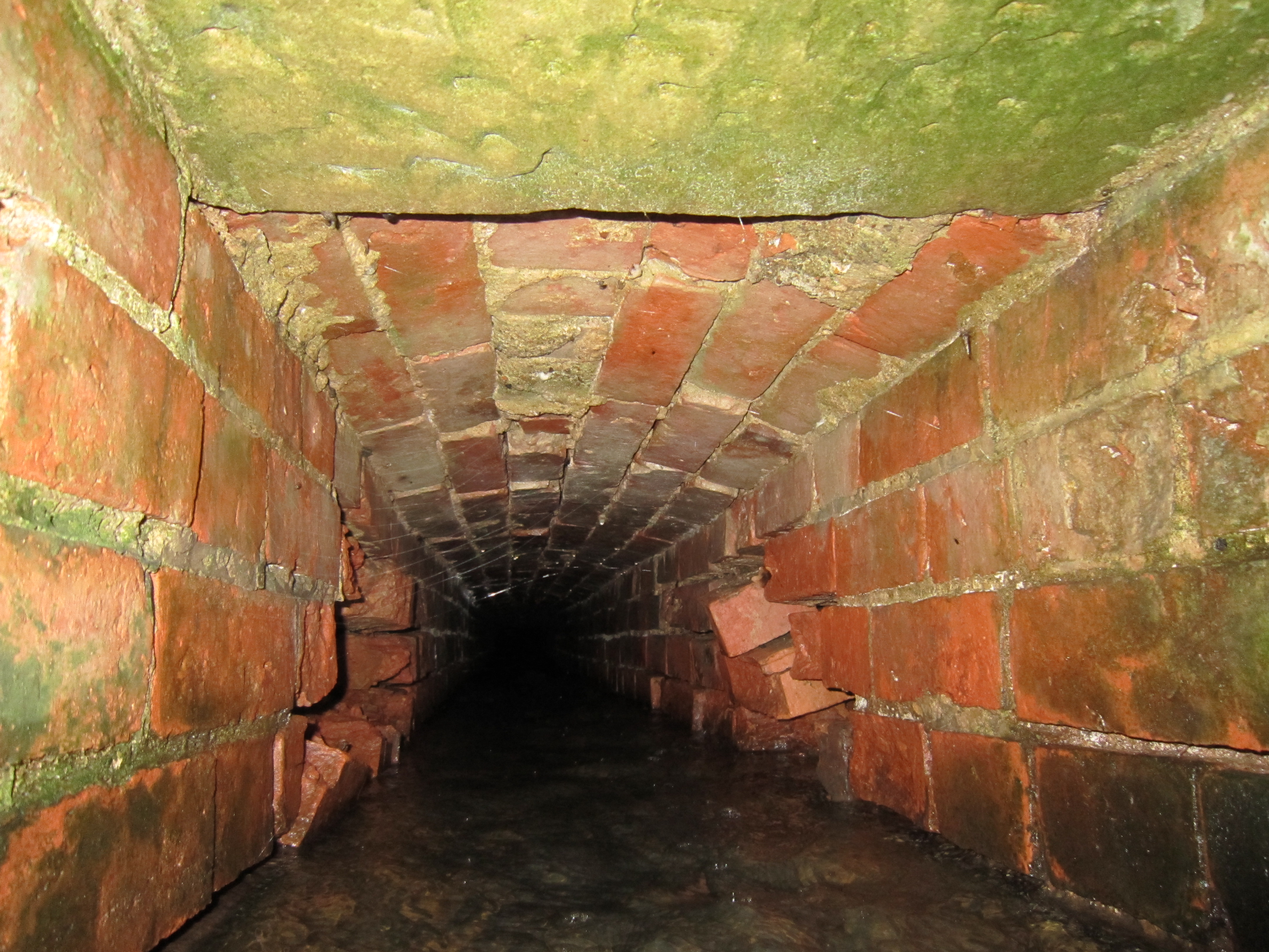
Drainage defects. Blocked ditches, silted toe drains, damaged crest drains, leaking carrier pipes and blocked culverts are often the root cause behind the visible earthworks problem rather than a separate issue. Water is usually the key factor. If it cannot get off or through the slope in a controlled way, the chances of erosion and instability rise quickly.
Settlement, heave and distortion. Embankments on soft ground can settle over time. Local settlement can alter the slope profile, disrupt drainage and create wet areas or depressions. Toe heave or outward spread can be a sign of foundation weakness or progressive instability. On some schemes the first obvious clue is not on the slope itself but in the verge, edge of carriageway or nearby drainage asset.
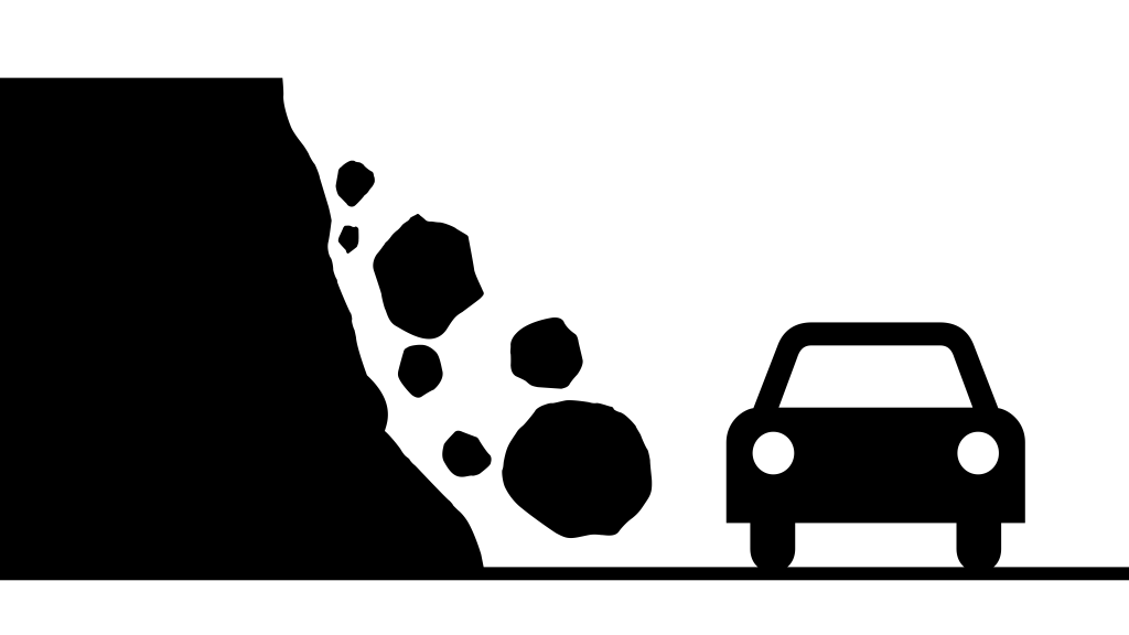
Rockfall and debris fall. In rock cuttings or mixed faces, deterioration may show as loose blocks, open joints, weathered wedges, overhangs or ongoing ravelling. Freeze thaw, water ingress, root action and past excavation geometry can all contribute. Even small volumes can be serious where traffic speed is high or there is little recovery space.
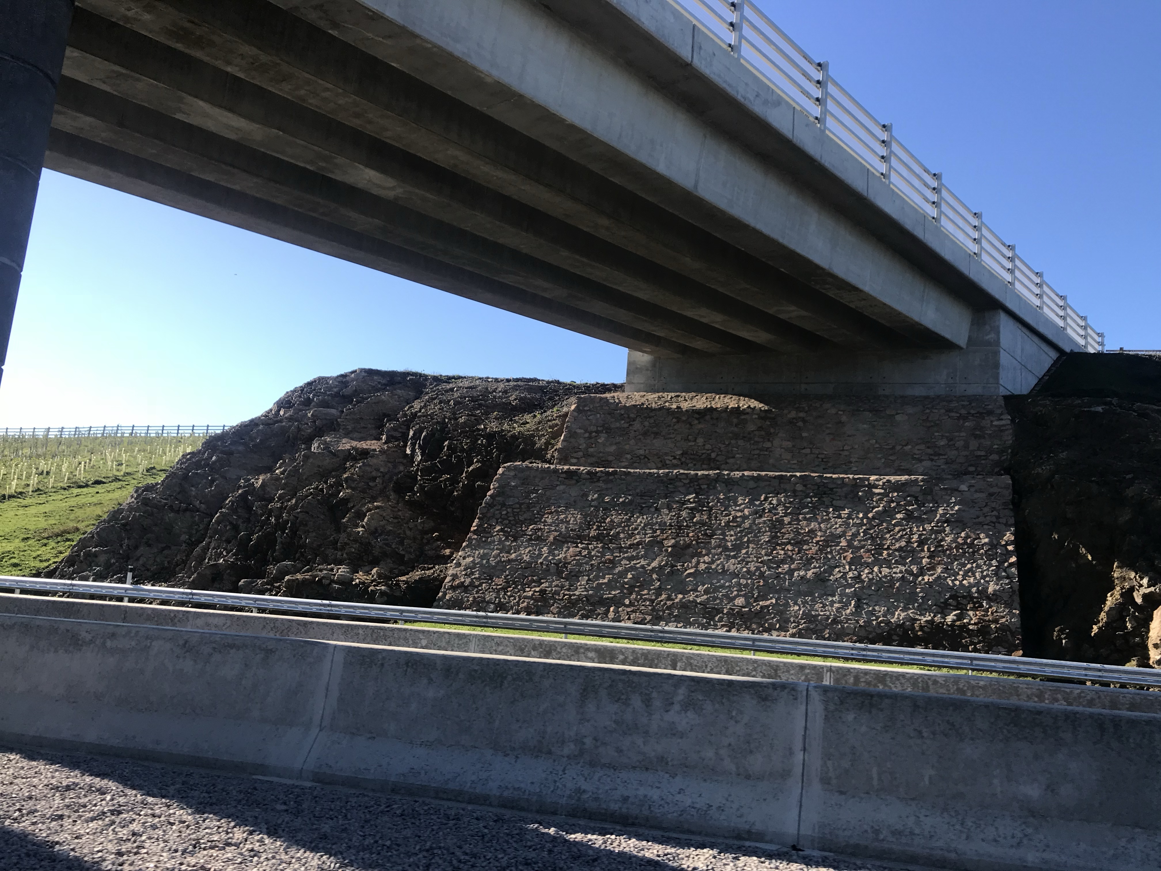
Distress in revetments and retaining systems. Stone pitching, concrete facing, gabions, reinforced soil facings and other systems are there to protect or support the slope. If units move, crack, open up or wash out, the material behind can begin to escape and the problem can develop quickly. These systems need to be looked at as part of the earthworks inspection, not as decoration.
What usually pushes these defects on?
Most earthworks defects are linked to one or more of the same factors: water, weak material, poor drainage, loss of support, poor original construction, vegetation issues, weathering and local changes in loading. Heavy rainfall is often the immediate trigger, but it is rarely the whole story. A slope usually needs an underlying weakness as well.
That is why the wet patch, the blocked ditch and the small crack matter. They are often the visible clues to a bigger geotechnical issue developing behind the face.
When does it become urgent?
There is no single national defect category that every authority uses in exactly the same way. The current UK approach is risk based. On local roads and the strategic road network, inspection and response times are set through the authority or network operator’s own regime rather than one universal list of earthworks defect codes.
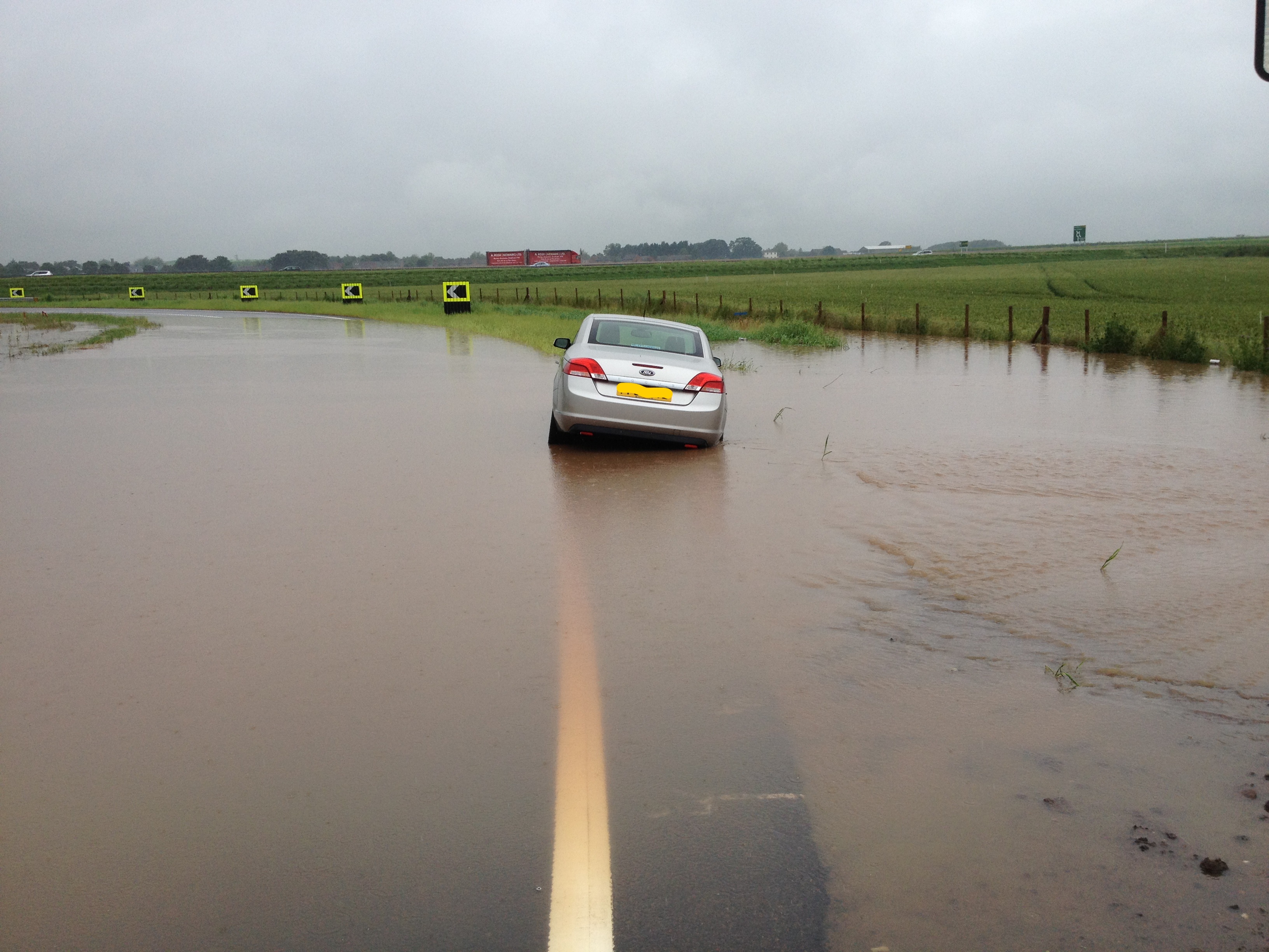
In practice, urgency rises sharply where there is active movement, fresh debris on the road, loss of support to the carriageway, blocked drainage causing flooding, visible rockfall risk, rapid crack growth or anything that suggests people could be exposed before the next planned visit. At that point the priority is to make the area safe, protect road users and get the right geotechnical input on site.
What does a useful first response look like?
The first response is usually not a permanent repair. It is to make the situation safe and stop it getting worse. That may mean traffic management, cordons, debris clearance, temporary drainage works, covering exposed ground, isolating a failed outfall or keeping water away from the crest.
After that, the permanent fix depends on the actual cause. Common measures include drainage improvement, reprofiling or resloping, erosion protection, reinstating lost toe support, repairing culverts and outfalls, replacing failed revetment, rockfall protection and, where needed, geotechnical strengthening such as nails, anchors, reinforced soil or retaining structures. Monitoring can also be a valid response where the defect is understood, currently stable and being actively managed.
The one trap to avoid is treating every slope defect as a surface problem. If the water, geometry or support issue remains, the defect usually returns.
What should the inspector record?
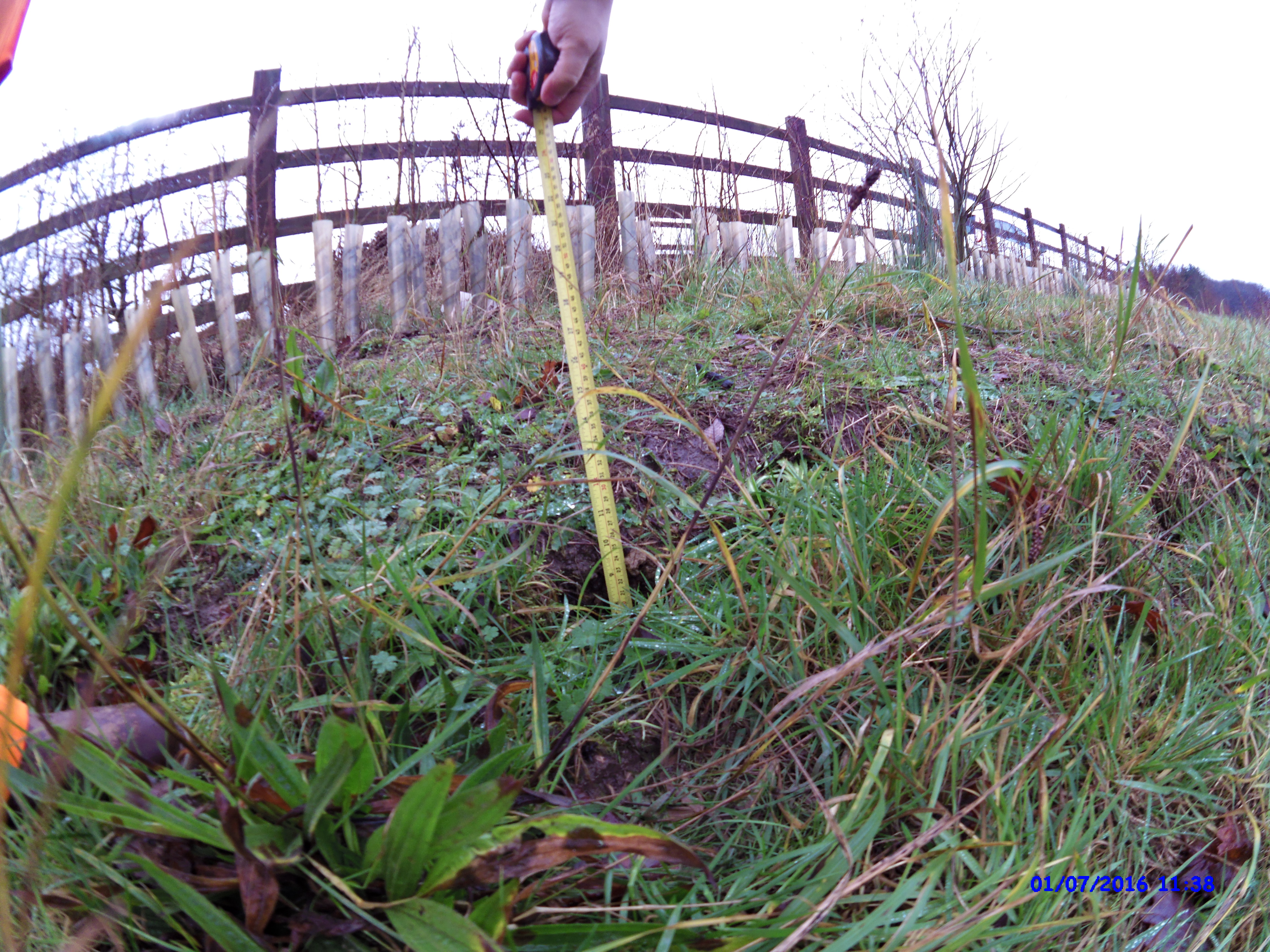
A useful record should cover the location, extent, likely failure mechanism, proximity to the carriageway, drainage condition, evidence of movement, recent weather, effect on other assets and whether the condition appears active or historic. Good photographs matter. So does context. A small crack on a dry stable slope is not the same as a small crack on a saturated embankment above a live lane.
If there is doubt, escalate it. Earthworks defects are one of those areas where under-calling the risk can become expensive very quickly.
Why this matters
Highway earthworks often deteriorate slowly, but they can fail suddenly. Regular inspection, decent records and early intervention, especially around drainage, make a real difference. Many failures start with signs that were visible well before the big event. The challenge is spotting them, understanding what they mean and acting early enough to keep a maintenance problem from becoming an incident.
Addendum: a practical earthworks defect checklist
People often ask what an earthworks defect checklist actually looks like in practice. The honest answer is that it is rarely as neat as a pothole threshold chart. With earthworks, the real issue is not whether something looks untidy. It is whether the slope is starting to lose stability, whether water is making that worse, and whether the defect could affect the road before anyone gets back to inspect it again. That is why earthworks are usually judged on risk, rate of change, location and likely consequence, rather than one simple national measurement rule for every defect.
Simple rule of thumb
Water + crack + movement + proximity to traffic = escalate fast.
So, if you wanted a simple A4 cheat sheet to carry on inspection, it might look something like this…
Earthworks defects quick check
Use this as a practical prompt, not as a substitute for your authority or client inspection policy. If in doubt, escalate. Earthworks defects rarely improve on their own.
Treat as urgent if any of the following are present
- Active slip, slump or bulge on an embankment or cutting
- Fresh tension crack at or near the crest of the slope
- Debris already on the verge, hard shoulder or carriageway
- Material that is clearly likely to reach the road before the next inspection
- Rapid deterioration after prolonged or heavy rainfall
- Any defect close enough to the carriageway that loss of support is a realistic concern
- Water issuing from the slope face, toe or a crack
- Blocked ditch, failed outfall or saturated toe area
- Retaining wall, gabion or revetment cracking, leaning, opening up or shedding material
- Trees, posts, fencing or signs tilting with the slope
- Exposed services or drainage damage caused by erosion or movement
- Loose rock, rockfall or undercut material above the highway
What to look for on every inspection
Surface condition
- Bare or exposed soil
- Rills, gullies or washout channels
- Loss of grass cover
- Soft or saturated patches
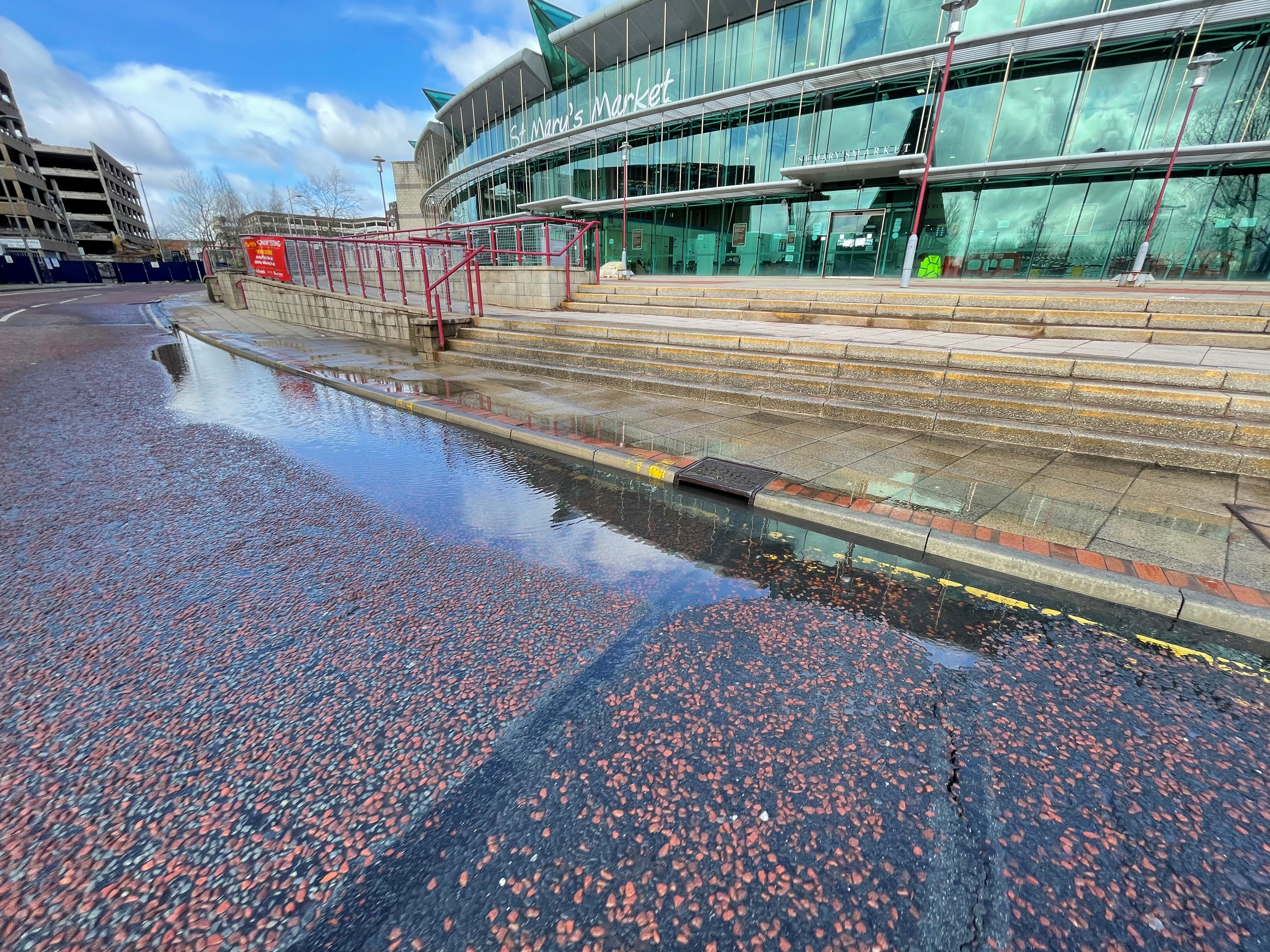
- Ponding or persistent wet ground
- Erosion at the toe or around drainage outfalls
Signs of movement
- Tension cracks
- Crescent-shaped scarps
- Bulging at the toe
- Uneven, stepped or hummocky ground
- Slumping or downward creep
- Settlement near the crest
- Dropped verge or shoulder line
Water and drainage
- Blocked ditch
- Blocked catchpit
- Standing water
- Seepage through the slope
- Wet patches in otherwise dry conditions
- Broken, displaced or surcharging outfalls
- Evidence of water tracking down the batter face
Vegetation and root issues
- Sudden vegetation stress
- Loss of established cover
- Heavy scrub or self-seeded growth affecting visibility or drainage
- Tree root disturbance to walls, revetments or drainage features
- Leaning or uprooted trees
Associated assets
- Leaning fence line
- Distorted safety barrier alignment
- Cracked retaining wall
- Failed gabion mesh
- Missing stone fill
- Exposed geotextile or erosion matting
- Damaged toe protection
A simple severity guide
Monitor or routine repair
This is where the defect is present but stable.
Typical signs include light surface erosion, minor local vegetation loss, shallow cosmetic cracking from drying, or minor drainage wear with no sign of ground movement. These defects still need recording and planned repair, but they are not usually an immediate threat to the road.
Priority defect
This is where the condition is getting worse or beginning to affect stability.
Typical signs include erosion that is deepening, localised slumping, widening cracking, softening at the toe, blocked drainage affecting the slope, small debris collecting in the ditch or verge, or the early stages of wall or gabion distress. These defects should not be left to drift. They need closer review and planned intervention before they become a live safety issue.
Urgent defect
This is where there is active movement, clear instability or a realistic risk to the highway.
Typical signs include a fresh slip, a growing crest crack, bulging, saturated ground with visible distress, debris reaching the road, retaining structure failure, or any condition that may become a live-road hazard before the next attendance. This is the point where the defect stops being a maintenance issue and becomes a response issue.
What to record every time
- asset type, such as embankment, cutting, batter, wall, gabion or revetment
- exact location and chainage
- side of road
- approximate height and length affected
- distance from the carriageway or hard shoulder
- defect type
- whether it appears to be changing
- whether water is present
- recent weather conditions
- whether drainage is functioning properly
- whether debris is present
- photos showing the wider context and the close-up detail
- any immediate action taken
First actions on site
Where safety is a concern, the first priority is always to protect the public and keep people away from unstable ground.
That may mean traffic management, coning, temporary barriers, an exclusion zone, or an urgent engineering review depending on the location and the defect. Loose material can sometimes be cleared safely, but unstable slopes should not be disturbed casually. If movement is suspected, geotechnical or engineering advice should be brought in early. Water-related defects should also be revisited after heavy rain, because that is often when minor warning signs become something more serious.
Final point
The defect itself matters, but the real question is always the same…
What could this become before the next person gets here?
That is the mindset that makes earthworks inspection useful. Not spotting that something looks rough, but recognising when a slope is beginning to tell you it is running out of tolerance.
Further reading: handy references for understanding earthworks
If you want to get beyond spotting defects and start understanding why earthworks behave the way they do, there are a few references worth keeping close to hand.
Some are formal highways standards. Some are practical safety guides. A couple go deeper into slope behaviour and geotechnical assessment. Together, they give a solid base for anyone involved in inspection, construction, maintenance or design.
1. DMRB geotechnics section
A good place to start if you work in highways. This is the main route into the current geotechnical standards used on the strategic road network. It helps put the whole subject in context and points you towards the core documents that deal with risk, maintenance and geotechnical management.
2. CD 622, Managing geotechnical risk
This is one of the most useful references if you want to understand how geotechnical issues should be approached on highway projects. It sets out the process for identifying, managing and recording geotechnical risk properly, rather than waiting for a problem to become visible on site.
3. CS 641, Managing the maintenance of highway geotechnical assets
This is the one to look at when the focus is existing assets rather than new design. It is particularly useful for embankments, cuttings and other earthworks already in service, where inspection, maintenance and deterioration are the real issues.
4. MCHW / SHW Series 600, Earthworks
If you want to know what good earthworks practice looks like in contractual and construction terms, this is one of the key references. It is the specification side of the story and helps explain what should be built, placed, compacted and controlled in the first place.
5. HSE guidance on excavations
This is a very practical read and well worth it. It covers collapse, support, battering, inspections, water ingress and working safely around excavations. It is written clearly and is a good reminder that ground can go from looking fine to becoming dangerous far quicker than many people expect.
6. HSE guidance on excavation and underground services
Also worth reading alongside the excavation guidance. A lot of earthworks problems and repairs sit right on top of buried service risk. This one helps keep that in view, especially where drainage work, slope trimming or local excavation is involved.
7. CIRIA C810, Natural slopes and landslides: condition, assessment and mitigation
This is a stronger technical reference for anyone wanting to go beyond surface symptoms and understand the mechanics of slope deterioration and failure in more depth. It is particularly useful where you are dealing with unstable ground, historical movement or longer-term mitigation.
8. CIRIA C574, Engineering in chalk
This is more specialist, but very useful where chalk is part of the ground profile. In some parts of the UK that makes it highly relevant. It helps with understanding chalk behaviour, classification and the implications for earthworks and cuttings.
A simple order to read them in
If you are starting from scratch, I would keep the order simple. Start with the HSE excavation guidance to get the safety fundamentals clear. Then move into the DMRB geotechnics material, especially CD 622 and CS 641. After that, look at SHW Series 600 for the construction and specification side. Once those are familiar, CIRIA is the next step if you want the deeper geotechnical understanding.
Final thought?
Earthworks are one of those areas where a bit of reading pays back quickly. The more you understand water, drainage, ground behaviour and early signs of movement, the more useful your inspections become.
You stop seeing a rough slope.
You start seeing what it might do next.


")
")